208
Chapter 18:
TI
FLASH
Studio
TI
-
89 / TI
-
92 Plus Developer Guide
Not for Distribution
Beta Version January 26, 2001
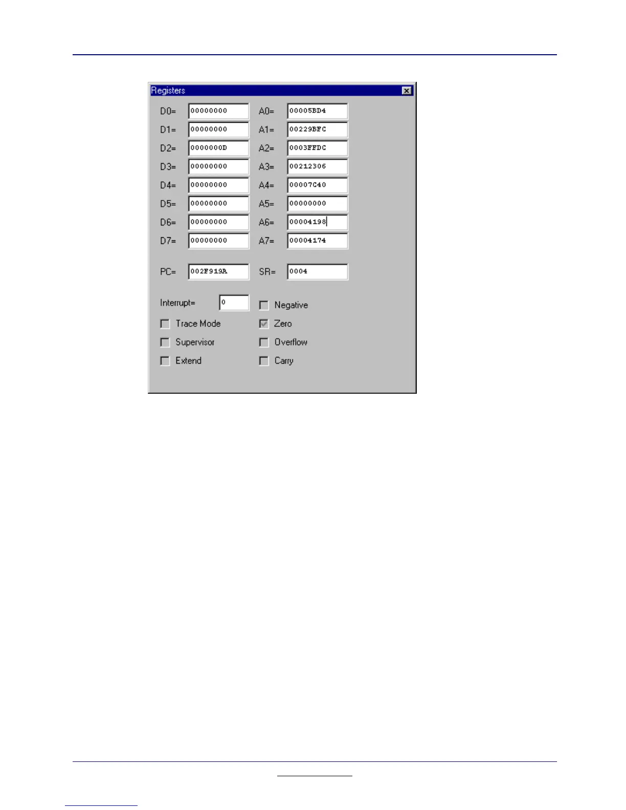
Figure 18.7: Registers
Column Information
D0 to D7 These fields represent the values of the eight 32-bit
general purpose data registers.
A0 to A7 These fields show the values of the 32-bit address
registers. The first seven registers (A0 to A6) and the user
stack pointer are used as software stack pointers and base
address registers.
PC Represents the 32-bit Program Counter.
SR Represents the Status Register. The SR contains the
interrupt mask (eight levels available) and the following
condition codes: overflow, zero, negative, carry, and
extend. Additional status bits indicate that the processor is
in the Trace mode and/or in the Supervisor state. See
Figure 18.8. Bits 5, 6, 7, 11, 12, and 14 are undefined and
reserved for future expansion.
 Loading...