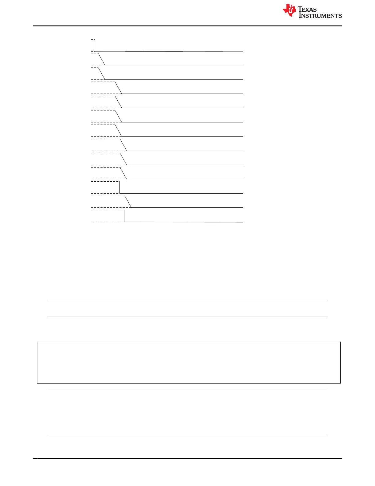
Resource PMIC Delay Diagram Total Delay Rail Name
LDO2
TPS65941421-Q1
(Leo B)
3500 us VDD_GPIORET_3V3
GPIO3
TPS65941421-Q1
(Leo B)
3000 us EN_DDR_VDD1
LDO1
TPS65941421-Q1
(Leo B)
2500 us VDD_WK_0V8
BUCK4
TPS65941421-Q1
(Leo B)
500 us VDD_DDR_1V1
FSM I2C Trigger
GPIO11
TPS65941120-Q1
(Leo A)
0 us
H_SOC_PORz
(nRSTOUT_SOC)
BUCK5
TPS65941421-Q1
(Leo B)
500 us VDD_RAM_0V85
LDO3
TPS65941421-Q1
(Leo B)
2500 us VDA_DLL_0V8
BUCK1234
LP876411B5-Q1
(Hera C)
2500 us VDD_CORE_0V8
BUCK1234
TPS65941120-Q1
(Leo A)
2500 us VDD_CPU_AVS
LDO4
TPS65941421-Q1
(Leo B)
3000 us VDD_PLL_1V8
BUCK1
TPS65941421-Q1
(Leo B)
3000 us VDD_IO_1V8
BUCK3
TPS65941421-Q1
(Leo B)
3000 us VDD_PHY_1V8
GPIO11
TPS65941421-Q1
(Leo B)
3500 us EN_3V3_VIO
I2C_6 = 0
I2C_7 = 0
I2C_6 = 0
I2C_7 = 0
Figure 6-7. PWR_SOC_ERROR with I2C Triggers low in both PMICs
6.3.6 MCU_TO_WARM
The MCU_TO_WARM sequence is triggered by a WATCHDOG or ESM_MCU error. The MCU_TO_WARM,
similar to the ACTIVE_TO_WARM sequence does not result in a state change. The event and sequence
originate from the MCU_ONLY state and stays in the MCU_ONLY state. In the sequence, the recover counter
(found in register, RECOV_CNT_REG_1) is incremented and the nRSTOUT (MCU_PORz) signal is driven low.
The MCU relevant BUCK and LDOs are reset to their default voltages at the time indicated in Figure 6-8, and
finally the MCU_PORz signal is set high after 2ms.
Note
GPIOs do not reset during the MCU warm reset event.
Also, at the beginning of the sequence the following instructions are executed to increment the recovery counter
and configure the PMICs:
// TPS65941120
// Set FORCE_EN_DRV_LOW
REG_WRITE_MASK_IMM ADDR=0x82 DATA=0x08 MASK=0xF7
// Clear nRSTOUT
REG_WRITE_MASK_IMM ADDR=0x81 DATA=0x00 MASK=0xFE
// Increment Recovery Counter
REG_WRITE_MASK_IMM ADDR=0xa5 DATA=0x01 MASK=0xFE
Note
The watchdog or MCU error is an indication of a significant error which has taken place outside
of the PMIC. The PMIC does not actually transition through the safe recovery as with an
MCU_POWER_ERR, however, in order to maintain consistency all of the regulators are returned
to the values stored in NVM and the recovery counter is incremented. If the recovery counter exceeds
the recovery count threshold the PMICs stay in the safe recovery state.
Pre-Configurable Finite State Machine (PFSM) Settings www.ti.com
42 TPS65941120-Q1, TPS65941421-Q1 and LP876411B5-Q1 PMIC User Guide
for J721S2, PDN-0A
SLVUCJ9 – FEBRUARY 2023
Submit Document Feedback
Copyright © 2023 Texas Instruments Incorporated
 Loading...


