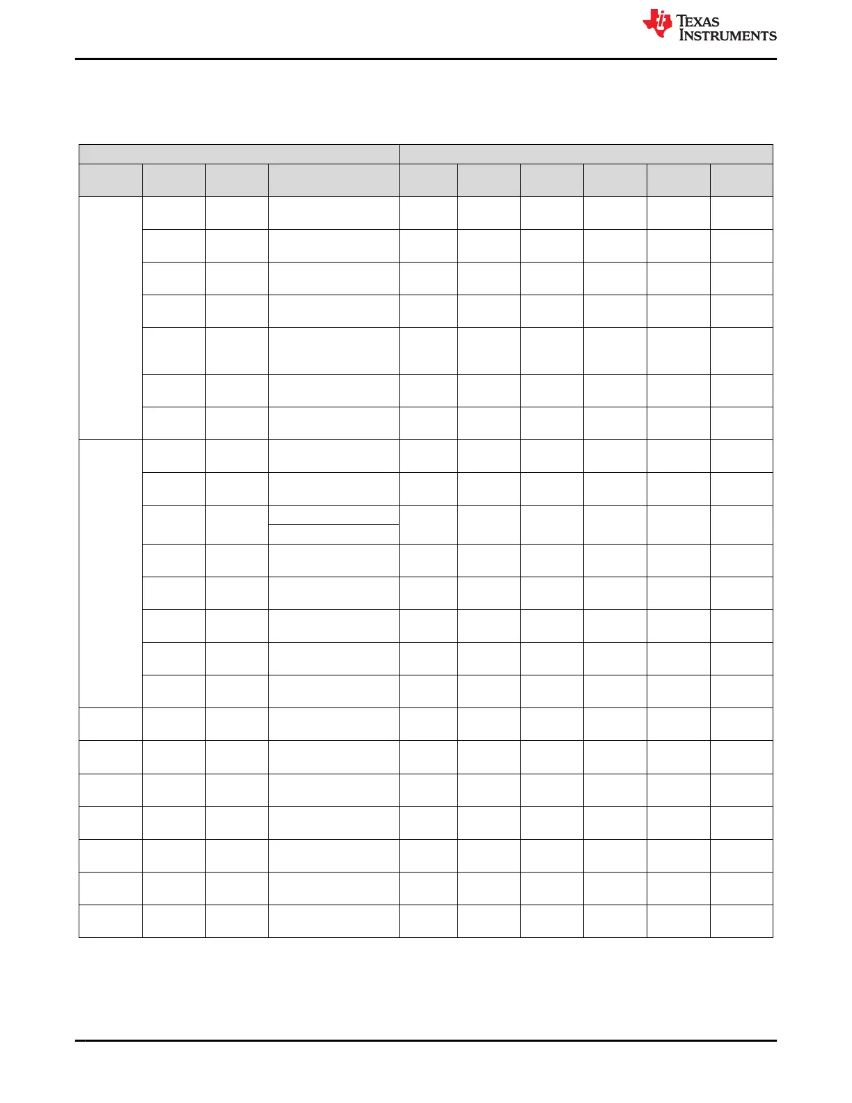
Table 3-1 identifies which power resources are required to support different system features. In the Active SoC
column, there are additional options for including or excluding the VPP_x(EFUSE) rail, the SD CARD rail, and
the USB rail.
Table 3-1. PDN Power Mapping and System Features
Power Mapping System Features
(1)
Device
Power
Resource
Power
Rails
Processor and Memory
Domains
Active
SoC
MCU -
only
GPIO
Retention
DDR
Retention
SD Card
USB
Interface
TPS65941
120-Q1
BUCK1234
VDD_CPU
_AVS
VDD_CPU R
FB_B3
VDDD_MC
UIO_3V3
VDDSHV2_MCU (3.3 V) R R
BUCK5
VDD_MCU
_0V85
VDDAR_MCU,
VDD_MCU
R R
LDO1
VDD_MCU
WK_0V8
VDD_MCU_WAKE1 R O
(2)
R
(2)
LDO2
VDD_MCU
_GPIORET
_3V3
VDDSHV0_MCU R O
(2)
R
(2)
LDO3
VDD_MCU
IO_1V8
VDDSHV1_MCU (1.8 V) R R
LDO4
VDA_MCU
_1V8
VDDA_x R R
TPS65941
421-Q1
BUCK1
VDD_IO_1
V8
VDDS_MMC0 R
BUCK3 VDD_PHY
_1V8
VDDA_1P8_x R
BUCK4 VDD_DDR
_1V1
VDDS_DDRx R O
(3)
R
(3)
Mem: VDD2, VDDQ
BUCK5 VDD_RAM
_0V85
VDDAR_x R
LDO1
VDD_WK_
0V8
VDD_WAKE0 R O
(2)
R
(2)
LDO2
VDD_GPI
ORET_3V3
VDDSHV2 R O
(2)
R
(2)
LDO3
VDA_DLL_
0V8
VDDA_0P8_x R
LDO4 VDA_PLL_
1V8
VDDA_1P8_PLLs R
LP876411
B5-Q1
BUCK1234 VDD_COR
E_0V8
VDD_CORE,
VDDA_0P8_x
R
TPS22965-
Q1
Load
Switch
VDD_MCU
IO_3V3
VDDSHV2_MCU (3.3 V) R R
TPS22965-
Q1
Load
Switch
VDD_IO_3
V3
VDDSHV0 (3.3 V) R
TLV73318
P-Q1
LDO VDD1_DD
R_1V8
Mem: VDD1 R O
(3)
R
(3)
TLV73333
P-Q1
LDO VDDA_3P3
_USB
VDDA_3P3_USB R
TLV103318
-Q1
LDO VDD_SD_
DV
VDDSHV5 R
TLV73318
P-Q1
LDO VPP_EFU
SE_1V8
VPP_x O
(1) 'R' is required and 'O' is optional.
(2) LDO1 and LDO2 of the TPS65941120-Q1 and LDO1 and LDO2 of the TPS65941421-Q1 remain on when TRIGGER_I2C_7, in
FSM_I2C_TRIGGERS register, is set.
(3) BUCK4 of the TPS65941421-Q1 and the TLV73318P-Q1 which is controlled by the TPS65941421-Q1 GPIO3 remain active while
TRIGGER_I2C_5, in FSM_I2C_TRIGGERS, is set.
Processor Connections www.ti.com
6 TPS65941120-Q1, TPS65941421-Q1 and LP876411B5-Q1 PMIC User Guide
for J721S2, PDN-0A
SLVUCJ9 – FEBRUARY 2023
Submit Document Feedback
Copyright © 2023 Texas Instruments Incorporated
 Loading...


