300/400TS and 300/400S 12 MAINTENANCE
12 – 9
3.3 PCB3 (WK-5548), PCB7 (WK-5550)
1) Remove the Side Panel. [Reference page : 11-1]
2) Remove the PCB4 (WK-4819). [Reference page : 12-10]
3) Remove the PCB6 (WK-5549). [Reference page : 12-11]
4) Remove the PCB5 (WK-5551). [Reference page : 12-11]
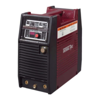
5) Disconnect the 11 connectors from the PCB3 (WK-5548).
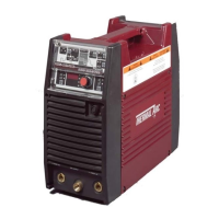
6) Loosen two screws. Rotate the Resistor (R7 and R8) to expose two screws on PCB3 (WK-5548).
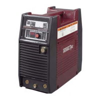
7) Remove the screw and then the four ground terminals. Remove the four screws and then remove the
PCB3 and PCB7 unit. Disconnect the three connectors from the PCB7 (WK-5550).
CN23
CN19
CN11
CN8
CN3
CN2
CN1
CN9
CN22
CN21
CN20
3
1
CN14
CN15
CN13
2
 Loading...