cutmaster 82
SERVICE 5-20 Manual 0-4980
F. Pilot IGBT Test
1. Disconnect wire from Main PCB terminal TIP1
2. Measure continuity on Main PCB between test point GND1 to terminal TIP1
3. If the test reveals a failed component, replace Main PCB. If no problem is found, reconnect wire to Main
PCB.
Signal Information
Many of the signal listed will be low voltage signals that will be in one of two states: +12VDC (High) or 0VDC
(Low) with respect to pcb common.. When a signal name is preceded by the “/” mark, it denotes that the signal
is an active low. For example:
/OVERTEMP – This signal is normally High but when an over temperature fault exists, this line will change
state to a Low.
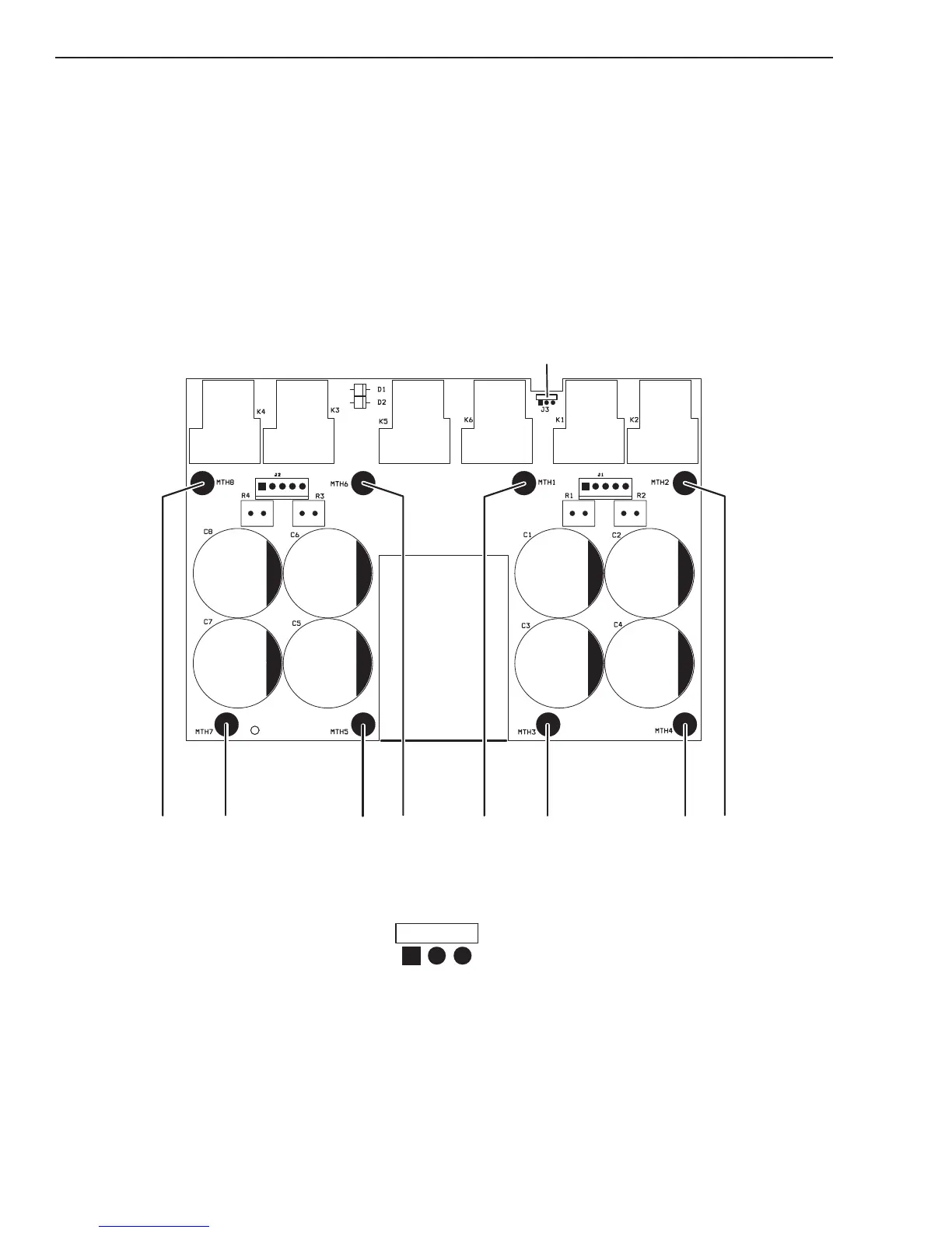
MTH8
MTH7 MTH5
MTH6
MTH1
MTH3
MTH4
MTH2
J3*
*J3 CONNECTOR PINOUT
1
2
3
Art # A-08841