Manual 0-2569 25 SERVICE TROUBLESHOOTING
120 VAC Test
NOTE
Refer to Appendix VII for 120 VAC Circuit Dia-
gram.
1. Check the voltage input from F2 (wire #10) to J6-9
for 100 - 120 VAC. Check the input from F2 to J6-
10 for 120 - 140 VAC.
2. If the voltage input is present, check the red LED
indicator (D18) on the voltage selection board. If
the indicator is lit, measure voltage output between
F2 (wire #10) and J6-7. If the indicator is not lit,
measure between F2 and J6-12. The voltage out-
put at either point should measure 110 - 130 VAC.
3. If both or neither J6-7 or J6-12 have high voltage
present, replace the voltage selection board. Check
voltage between J6-14 and wire #10 on fuse F2 for
110 - 130 VAC. This supplies 120 VAC to the rest
of the unit.
B. Enable Circuit Tests
Coil voltage of 120 VAC is supplied to the Motor Contac-
tors (MC1 and MC2) and the Main Contactors (W1 and
W2) through the Voltage Selection PCB (refer to Section
4.05-A and Appendix VII). The return path is through
the Switching Control PCB Enable Relay (K1), the ON/
OFF Switch (SW1-A) and the 5A fuse (F2).
Shutting off the Enable removes power from the pump
motor, fan motor and the DC power to the torch.
Enable Relay K1 is energized by the following:
• ENABLE SW on the RC 6010 via J15-32 and J15-33
or
• By a switch connected to TB2-1 and TB2-2
ENABLE signal to the Slave Power Supply also comes
from TB2 in the Master Power Supply. The signal goes
through the Isolation PCB to the Parallel Connector, J54.
Signal then goes through the Parallel Cable to J15 on the
Slave Power Supply. Refer to Section 4.05-T, Isolation
PCB and Parallel Interface.
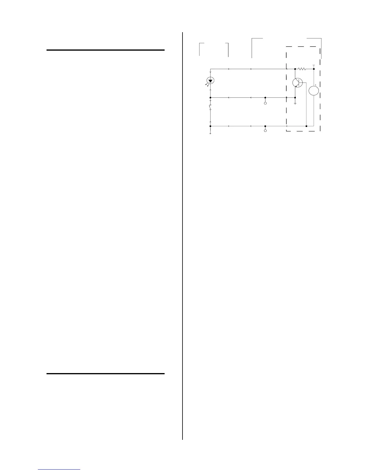
Check Enable Relay K1 circuit per the following:
NOTE
This procedure applies to both the Master and Slave
Power Supplies:
A-01137
K1
RC6010
Switching
Control PCB
ON
ENABLE
To AMP/VOLT
Display Enable
TB2-2
J1-5
J1-4
E2
E3
J37-17
J15-5 J50-12
J50-10
J15-33
J37-27
J37-26
J15-32
TB2-1
J50-11
Merlin 3000, 6000
or 6000GST
+V1
Figure 4-3 Enable Circuit Diagram
1. Check for zero AC volts from F2, wire #10, to J7-22
and from F2, wire #10, to J7-24.
• If voltage is correct, the Enable Relay is closed.
The fault is in the contactor (refer to Section
4.05-D, Motor Control Contactor Check) or the
voltage supply (refer to Section 4.05-A, Volt-
age Selection PCB Checks).
• If voltage, approximately 120 VAC, is present
at J7-24 the circuit is open between J7-24 and
F2. Check Fuse F2 or ON/OFF Switch for open
condition.
• If there is about 120 VAC at J7-22 then Enable
Relay K1 is not closed, proceed to next step.
2. Check for the +15 vdc relay power supply, +V1, on
the Switching Control PCB. Measure between TP1
and TP2 on the Switching Control PCB. Should
be about +15 vdc at TP2.
• If voltage is not correct, power may not be get-
ting to the PCB or there may be a short either
on or off the PCB.
3. Check for 14 to 18 VAC incoming power by mea-
suring from TP1 to J7-12 and J7-15.
• If voltage is not correct, refer to Section 4.05-A,
28VAC tests.
To check for shorts, remove J9, J10 and J50 from
the Switching Control PCB. Also, remove J70 from
the Signal Isolation PCB.
Check for +15 vdc from TP1 to TP2.
• If voltage is incorrect, then the PCB may be
faulty, proceed to next step
 Loading...


