SERVICE TROUBLESHOOTING 26 Manual 0-2569
• If voltage is correct, then reinstall the connec-
tors one at a time to isolate the problem. In the
case of a ribbon cable the cable itself may be
shorted.
4. Voltage is correct at TP2
If the Remote Control RC6010 is being used, tem-
porarily jump TB2-1 to TB2-2. If the fan and pump
come ON the problem is in the Remote Control
enable circuit.
Check continuity from TB2 back through J15 and
the remote cable to the remote Enable Switch to
find the problem.
If jumping TB2 did not work, check continuity
from TB2, wires #102 and #103 to J50-10 and J50-
11. If correct, replace the Switching Control PCB.
C. Blown Fuse (F1 or F2)
1. A shorted or frozen motor will cause F1 to fail. To
check the motors, disconnect J20 (pump motor)
and J39 (fan motor). Reconnect one at a time to
determine which component is faulty. A shorted
or open fan motor starting capacitor (C32) may
also cause F1 to fail.
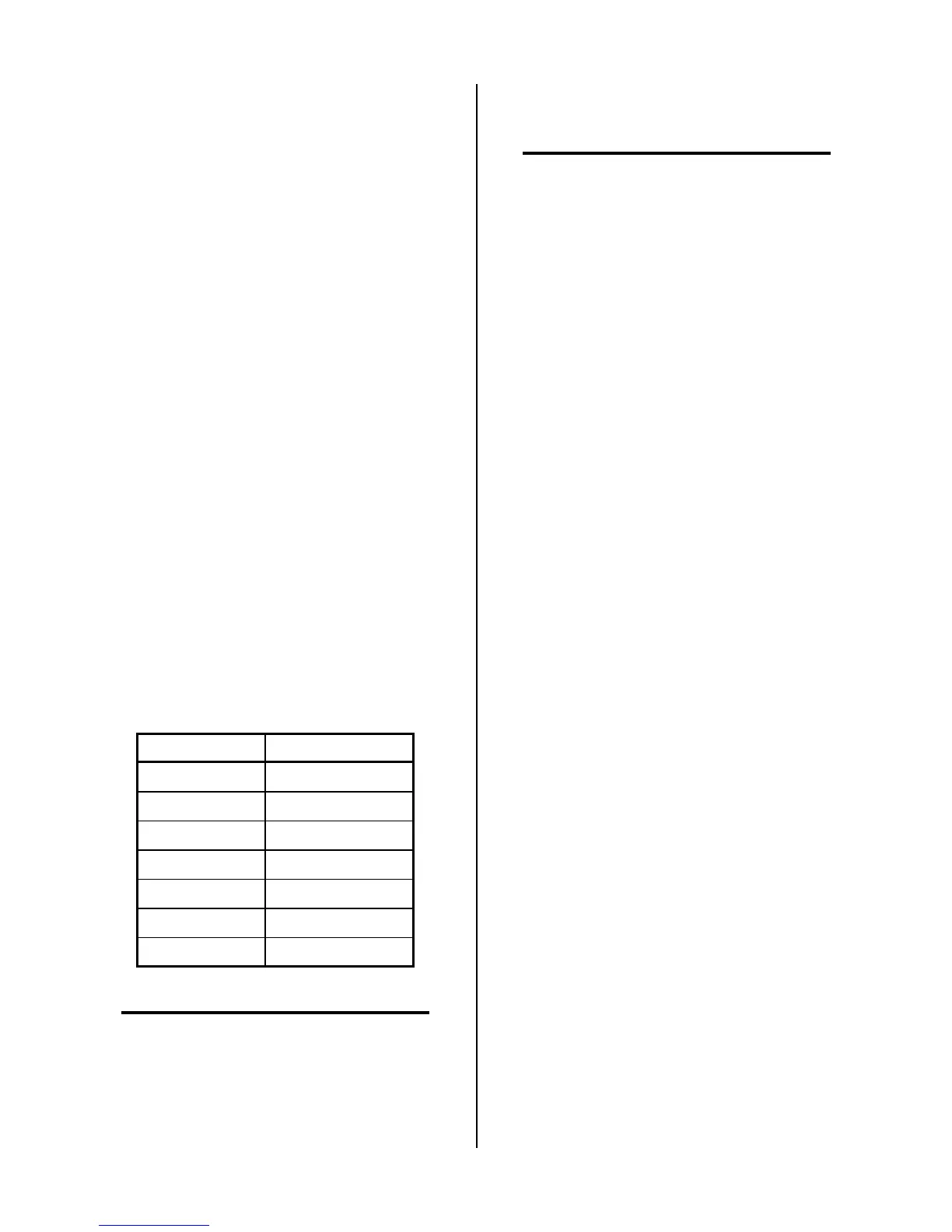
2. F2 fuses the 120 VAC circuit. MC1 or MC2, T2, T3
and the gas solenoids are energized when power
is first applied. If shorted, any one of these com-
ponents would cause F2 to fail. W1 or W2, and
PCR energize after the torch switch or remote start
switch is activated. The resistance for each of these
components is as follows:
Component Resistance (ohms)
T2 9
T3 2
MC1 7
MC2 7
W1 16
W2 16
PCR 58
NOTE
Refer to Section 4.05-H for checking Solenoids.
Check the resistance of each component or dis-
connect all the components and reconnect one at
a time to determine which component causes the
fault.
D. Motor Control Contactor Check (MC1, MC2
or MC3)
NOTE
Refer to Appendix VII for 120 VAC Circuit Dia-
gram.
1. Motor Contactor MC1 and MC2
The 120 VAC is supplied to the Motor Control Con-
tactor (MC1 and MC2) coils from the Voltage Selec-
tion PC Board, which selects the proper tap on the
Main Transformer (T1). The return path travels from
wire #110 through K1 on the Switching Control PC
Board to wire #8, through the ON/OFF switch (SW1A)
to wire #9, through fuse F2 to wire #10 and T1.
Only one of the two contactors should have voltage
applied. If the red LED indicator (D18) on the volt-
age selection board is lit, MC2 should be energized.
If D18 is not lit, MC1 should be energized.
a. Check the voltage across the coil on the contactor
for approximately 120 VAC. If voltage is present,
replace the contactor. If it is not, perform the 120
VAC test (refer to Section 4.05-A) to check for a
proper voltage supply from the voltage selection
board. If correct, continue to step 2 to isolate the
problem in the return path.
b. With one meter lead on the supply side of the con-
tactor coil (wire #3 for MC1 or wire #4 for MC2)
measure to wires #8, 9, and 10 to determine where
the return circuit is broken. On the return path, F2
and SW1-A can be measured for continuity. En-
able Relay, K1, on the Switching Control PC Board
will normally be open when power is OFF. Refer
to Section 4.05-B for Enable Circuit Checks.
2. Motor Control Contactor MC3
The function of Motor Control Contactor MC3 is to
turn on the Pump Motor if the unit is a Master Power
Supply and turn it OFF when a Master Power Supply
is used as a Slave Power Supply. Contactor MC3 looks
identical to MC1 and MC2 but it’s coil is 12 vdc, while
MC1 and MC2 coils are 120 VAC. The 12 vdc power
comes from the Logic PCB, J4-7. Ground is applied
from Logic PCB J4-8.
a. If the Fan is running but the Pump is not, contactor
MC3 may be faulty.
Check for about 12 vdc across Motor Contactor
MC3 coil.
• If voltage is correct, proceed to step b.
• If voltage is incorrect, proceed to step c.
 Loading...


