SERVICE TROUBLESHOOTING 42 Manual 0-2569
Pulser
99
150
Wire #99
Tap
9.0 ohms
At End
R16 (4.5 ohms)
R22 (2.2 ohms)
R21 (2.2 ohms)
Temp Switch
Wire
#96A
Wire #150
Tap
Wire #74
8.5 ohms
12.8" (305 mm)
8.0 ohms
11.2" (279 mm)
7.5 ohms
9.6" (242 mm)
7.0 ohms
8.1" (203 mm)
6.5 ohms
6.5" (164 mm)
6.0 ohms
5.0" (127 mm)
5.5 ohms
3.4" (87 mm)
5.0 ohms
1.9" (44 mm)
4.4 ohms
At End
Wire #96
4.4 ohms
At End
5.0 ohms
13.7" (344 mm)
5.5 ohms
12.3" (311 mm)
6.0 ohms
10.8" (255 mm)
6.5 ohms
9.4" (237 mm)
7.0 ohms
8.0" (203 mm)
7.5 ohms
6.5" (164 mm)
8.0 ohms
5.1" (127 mm)
8.5 ohms
3.7" (90 mm)
9.0 ohms
2.5" (63 mm)
A-01852
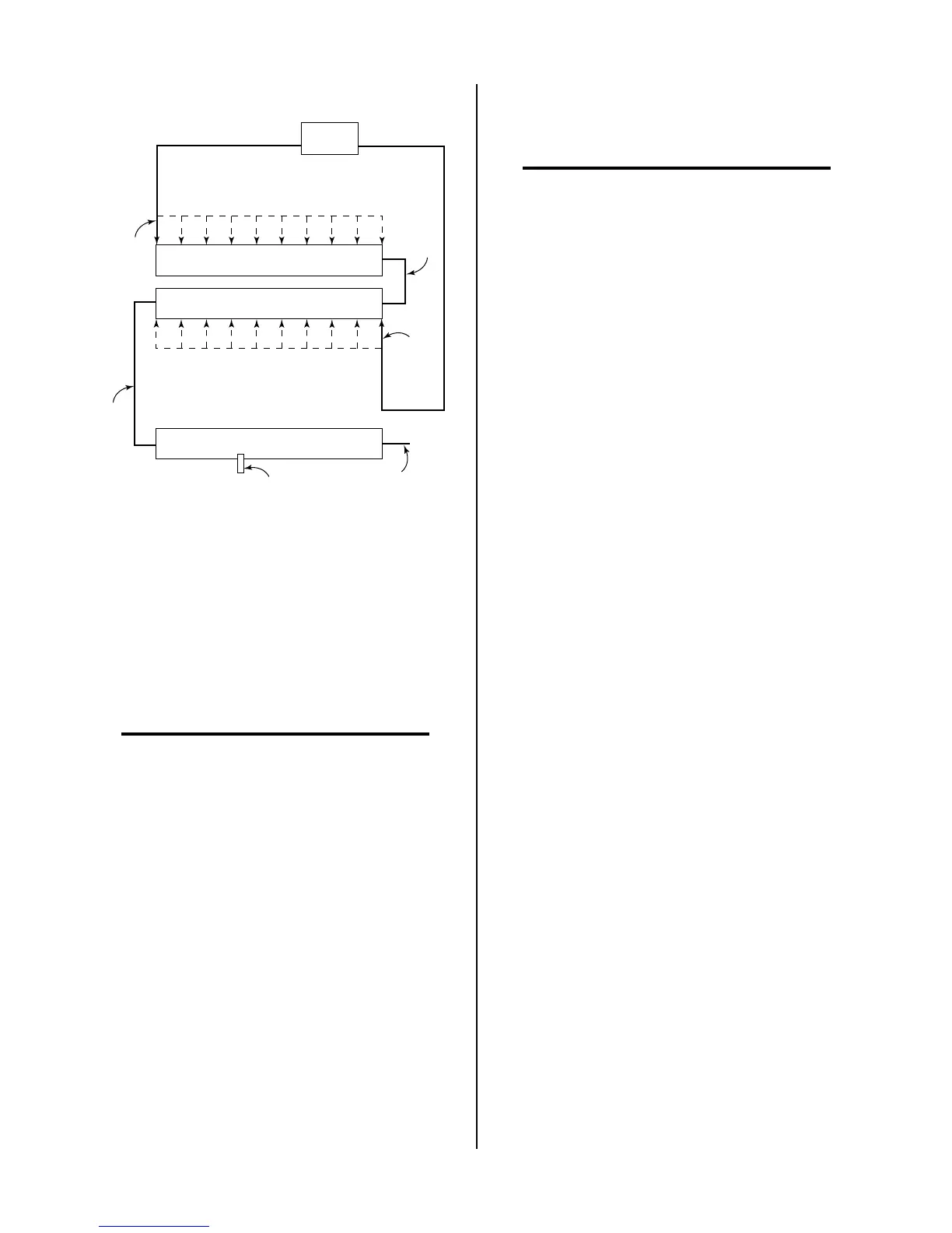
Figure 4-5 Resistance Value Diagram
7. The pilot pulse value is set by positioning the wire
#150 tap on resistor R22. Locate and loosen the
wire #150 tap. From the above Figure find the
ohms value that corresponds to the value that the
wire #99 tap was set to. Measure distance indi-
cated from the right side of R22, where wire #96
attaches and secure the wire #150 tap there.
NOTE
The ohm value shown for the wire #150 tap does
not represent the value of the R22 resistor but in-
stead corresponds to the total resistance of R16,
R22 and R22 set by the wire #99 tap.
8. Test the pilot, if it still sputters move the wire #99
tap to the right, toward wire #96, 1 inch (25.4 mm)
at a time until the pilot no longer sputters.
9. Once there is a good steady pilot, test for the de-
sired transfer height. If the transfer height is not
high enough, between 3/8 inch (9.5 mm) to 1/2
inch (12.7 mm), move the wire #150 tap to the left
on R22, 1 inch (25.4 mm) at a time, until the de-
sired height is obtained.
T. Isolation PCB and Parallel Cable tests.
The Slave Power Supply is controlled from the Master
Power Supply. There are three digital, ON or OFF, sig-
nals and two analog, voltages of varying levels, signals
that must be passed between the two units. These sig-
nals have to be electrically isolated between the two units.
The Isolation PCB in the Master Power Supply accom-
plishes this using both digital and analog optoisolator
intergated circuits (IC).
NOTE
For a simplified diagram, refer to Appendix XXI,
Parallel Interface Diagram.
The circuits on each side of the isolation barrier require
their own power supply. On the Master Power Supply
side, unregulated, approximately 20 vdc, from J7-14 of
the Master Power Supply Switching Control PCB goes to
J70-3 of the Isolation PCB to power a regulator for +V1,
+15 vdc. On the Slave Power Supply side, voltage from a
20 ma current source on the Slave Power Supply Switch-
ing Control PCB is applied through the Parallel Cable (J15-
30 to J54-5) to a zener diode for +V2, +15 vdc. The two
supplies, as well as the circuits they operate, are com-
pletely isolated from each other.
Two digital signals, ENABLE and START TO SLAVE and
one analog signal, DEMAND TO SLAVE, 3.3 to 10 vdc,
go from the Master Power Supply to the Slave Power
Supply. One digital signal, SLAVE IS ON and one analog
signal, OUTPUT SIGNAL TO MASTER, 0 to 10 vdc, go
from the Slave Power Supply to the Master Power Sup-
ply.
Both the inputs and outputs of the digital signals are low
when the signal is ON and high when signal is OFF. The
diagram at Appendix XXI, Parallel Interface Diagram,
shows the expected voltages. 14 vdc / 1 vdc indicates
when the signal is OFF (high) it should be 14 vdc and
when ON (low) it should be 1 vdc. If an input is correct
and the output is not, the Isolation PCB is probably faulty,
although the circuit that the signal goes to could be load-
ing it down.
The ENABLE signal should be ON whenever the Master
Power Supply ENABLE is ON. The START signal comes
ON when the Master Power Supply contactor comes ON,
at the end of the Master Power Supply pre-flow. The
SLAVE IS ON signal should be ON when the Slave Power
Supply is powered ON even if it’s not enabled.
The analog outputs should be the same as the analog in-
puts. If the output is low and power supply (+V1 or +V2)
is correct the Isolation PCB is faulty.
 Loading...


