TK 56430-18-IP-EN
79
Section 9 - Configuring Software and Controller
Procedures
Controller Overview
This chapter is a high level overview of the controller. The installer should refer to the DSR III Diagnostic Manual (TK
61096) for more detailed instructions on diagnostics, repair, and operation.
Two different controllers are used on VP truck units: the DSR II and DSR III.
DSR II Controller
DSR III Controller
• The DSR II and DSR III Controllers are not interchangeable as the pin-outs, mounting pattern, and harness
connecting them to the unit are different.
• The controller’s fuses are different for 12 Vdc and 24 Vdc configurations. See the unit specific installation manual’s
wiring schematic for exact fuse values.
• The DSR II and DSR III Controllers both use the same DSR In-Cab Display.
• The DSR II and DSR III controllers have different firmware (software) that programs the controllers.
– The DSR II controllers have version 338800..1100 loaded from the supplier.
– The DSR III controllers have version 554444..0033 loaded from the supplier.
• All DSR controllers require a configuration file that is dependent oonn bbootthh tthhee ffiirrmmwwaarree vveerrssiioonn aanndd ttyyppee//ffaammiillyy ooff
uunniittss. Example: V520RT MAX 50.
NNOOTTIICCEE
EEqquuiippmmeenntt DDaammaaggee!!
IInnssttaalllliinngg tthhee iinnccoorrrreecctt ccoonnffiigguurraattiioonn ffiillee ccaann rreessuulltt iinn ddaammaaggee ttoo tthhee uunniitt..
NNoottee:: Refer to (“Configuration Files,” p. 83) for the loading procedures.
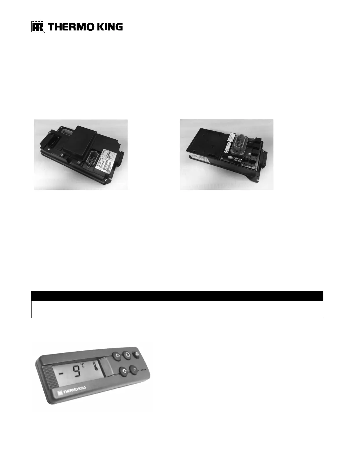
Figure 71. DSR In-Cab Display