2-43
C3544
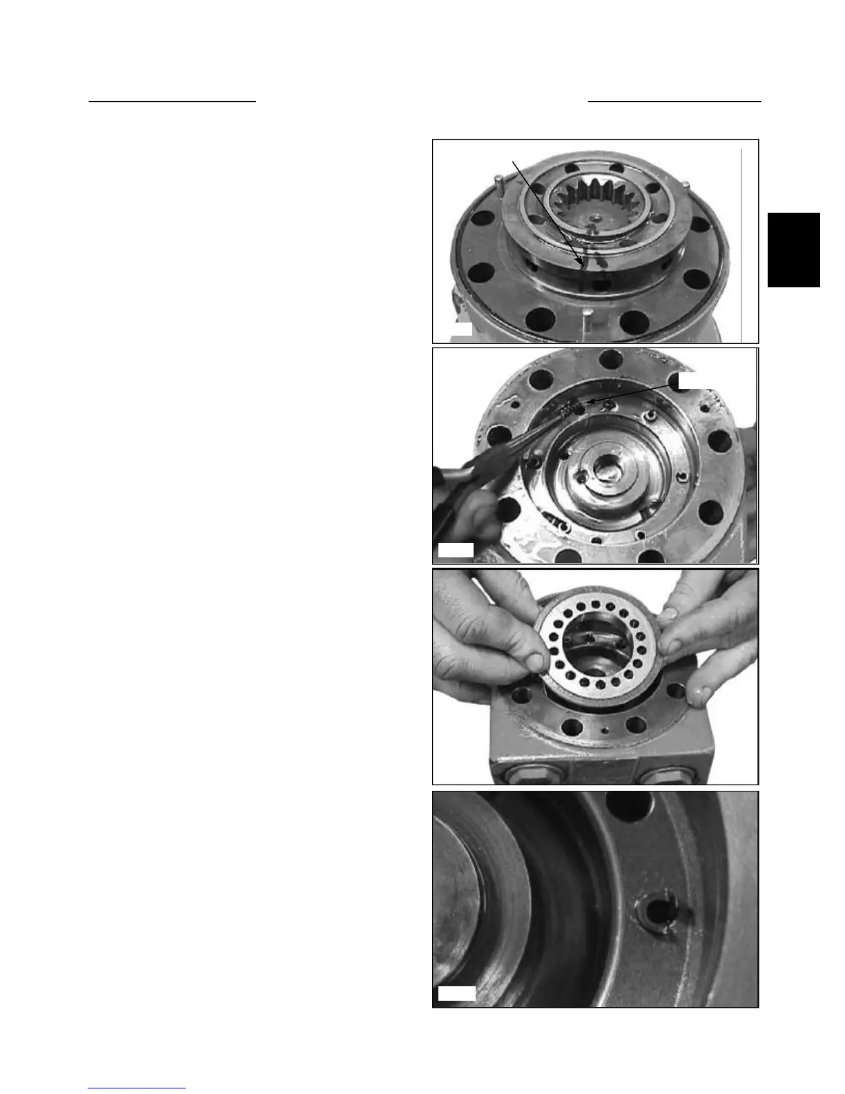
13 The timing is critical as the gearwheel valley cannot
be seen. Use a marker point as a guide to offest 1 tooth
counter-clockwise to the disk valve (fig. C3544).
C3545
C3546
C3547
Marker Guide
Springs
15 Inspect the O-ring seals, and if needed, replace.
Install the balance plate and use guide pin for alignment
(fig. C3546).
DRIVE MOTOR 2.11
14 In the valve housing, install the 6 springs in the
drilled holes (fig. C3545).
16 Example of an incorrectly installed balance plate.
The guide pin becomes damaged and the balance plate is
not locked into position. This can cause it to spin and ren-
der the motor non-functional (fig. C3547).