3-6
Chain Installation
DRIVE CHAIN 3.3
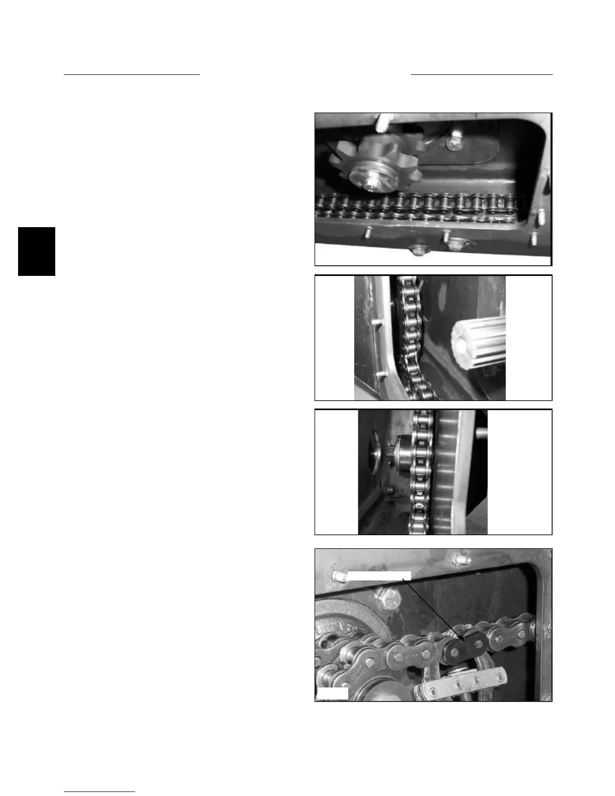
1 Install the wrapped chain into the final drive housing.
(fig. C3812)
C3809
C3812
C3522
5 Install a new connecting link. (fig. C3522) Place the
connecting link into the chain so the cotter pins face the
inspection cover hole. Bend the ends of the cotter pins at
least 90 º apart.
6 Replace the inspection cover using the gasket. Do not
over tighten the inspection cover nuts. 11 lbs / ft maxi-
mum. (15.0 nm)
7 Replace the wheels and torque the wheel nuts to 100
to 110 lbs/ft. (136 to 149 nm).
Connecting link
2 Place one end of the front chain over the top of the
front axle sprocket. Rotate the axle and bring the chain
along the bottom of the final drive housing to approxi-
mately the center. (fig. C3809) Wrap the other end of the
chain around the motor sprocket teeth closest to the
motor.
3 Place the ends together and install the new connect-
ing link so that the cotter pins face away from the inspec-
tion cover. (fig. C3810). Bend the ends of the cotter pins
at least 90 degrees.
4 Wrap the rear chain over the rear axle sprocket.
Rotate the axle and chain around the bottom of the final
drive housing and around the bottom of the motor sprock-
et closest to the inspection cover opening until the ends of
the chain meet together.
C3810