5-20
SAFETY CIRCUIT 5.10
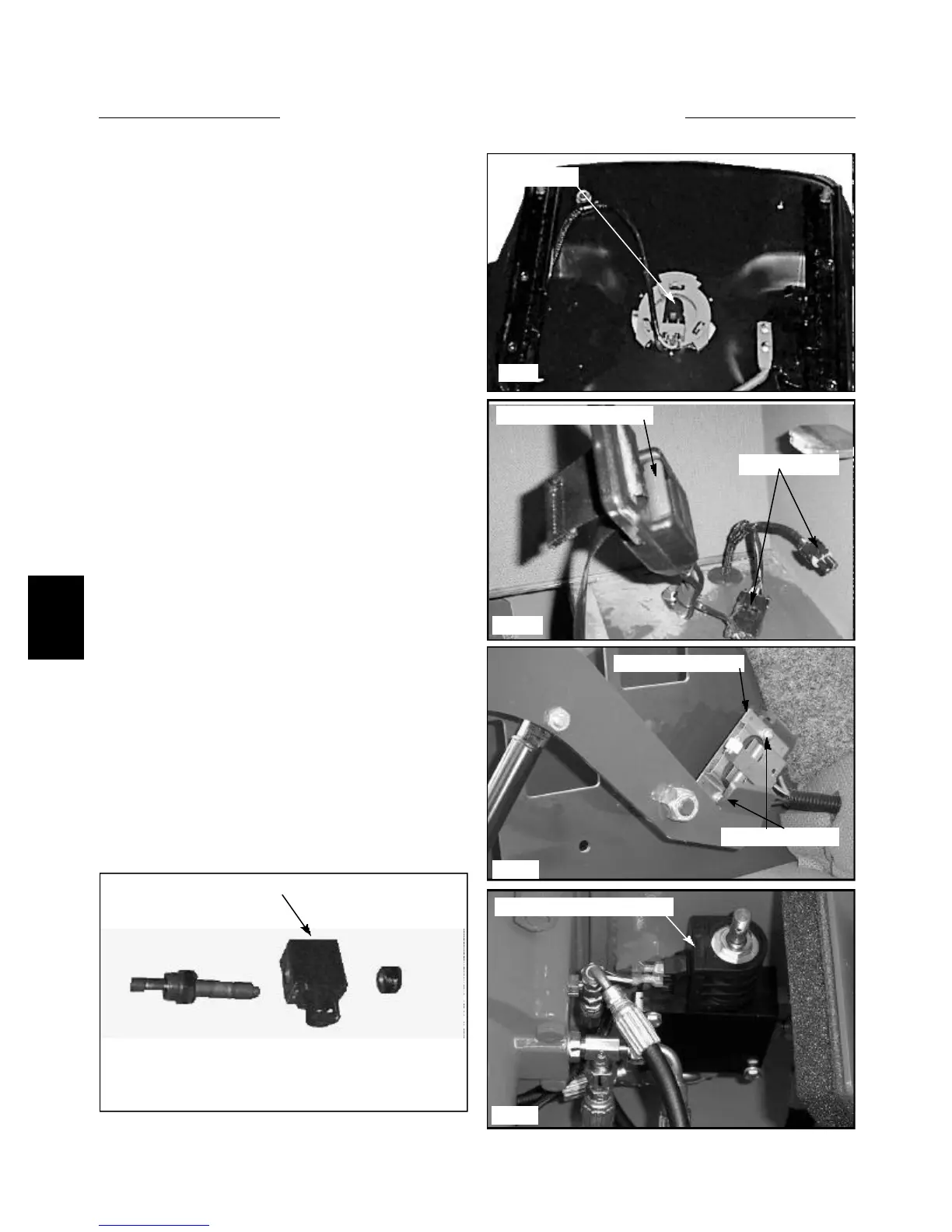
C807
C3879
C3573
C1514
C3575
Seat switch
Seat belt latch & switch
Harness plugs
Restraint bar switch
Parking brake solenoid coil
Control valve lock solenoid coil
General Information
The loader is equipped with 3 inter - connected safety
switches. These 3 switches operate 2 electric solenoid
controlled lock devices. One (1) solenoid coil on the
hydraulic brake valve (fig. C3575), one (1) pair of sole-
noid coils on the hydraulic control valve (fig. C1514)
Failure of any one (1) of these switches will prevent the
operation of the solenoid coils and loader functions. All 3
must be hooked up, functioning and, if applicable, adjust-
ed correctly.
The bottom of the operators seat is equipped with a pres-
sure sensitive switch. The operator must be in the seat to
close the switch and release the parking brake and unlock
the control valve functions. (fig. C807) No adjustments
required. When removing and replacing the seat, be sure
not to pinch the wires under the seat plate.
The seat belt assembly is equipped with a safety switch.
The operator must have the seat belt fastened around
them in order to close the switch and allow the parking
brake to release and the control valve to function. (fig.
C3879) No adjustments required.
The restraint bar is equipped with a dual function safety
switch. (fig. C3573) With the restraint bar in the raised
position, the parking brake is activated, the control valve
functions are locked and the activation indicator lights are
illuminated on the dash panel.
Lowering the restraint bar releases the parking brake,
turns off the indicator lights in the dash panel and releas-
es the locks in the control valve.
The restraint bar must be in the lowered position for the
control functions to operate.
The switch must contact the restraint bar when in the
lowered position.
Mounting screws