2-37
DRIVE MOTOR 2.11
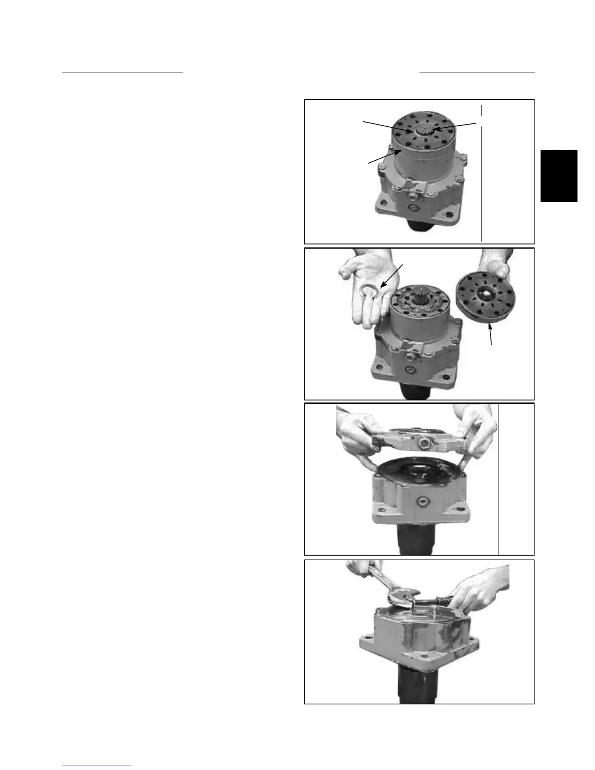
12 Remove the retaining ring, then the channel plate,
and then lift off the drive shaft which will then expose the
gearwheel and the Cardon shaft. (fig. C3518)
C3518
C3517
C3525
3526
Disassembly (cont’d)
13 With the drive section removed, losen the eight (8)
brake cover screws and lift off the housing to expose the
“spring” plate. (fig. C3525, C3526))
Drive Shaft
Channel
Plate
Retaining
Ring
RetainingRing
Channel Plate