34
34
NV10P - Manual - 01 - 2015
CHARACTERISTICS
Reset LEDs
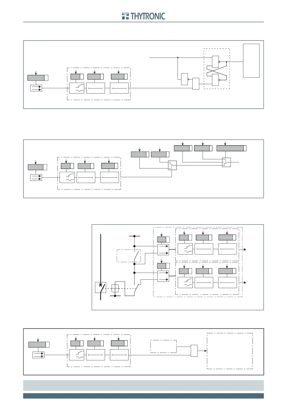
If the element tripped have gone back to rest condition, the latched LEDs and/or relays may be cleared.
Set profi le
Inside PRO-N devices, two independent setting profi les (A and B) are available. Whereas different
settings are required, they are made in the setting profi les and stored in the non volatile memory of
relay. Applicable setting profi le is activated usually via a binary input; when the programmed input is
activated, the profi le B becomes operative as a replacement for the default profi le A.
[1]
TCS1 and TCS2
Trip Circuit Supervision.
Supervision with one or two binary input can be performed.
The exhaustive treatment of the TCS function is described in the concerning paragraph.
Fault trigger
When the programmed input is activated, a trigger is issued for fault record SFR). Data storing takes
place with the same procedure resulting from a trip of any protective elements.
Note 1 To enable the profi le switching the “Input-selected” parameter must be set inside the “Profi le selection” submenu.
If multiple setting groups are not required, Group A is the default selection
Reset-led.ai
TRIPPING MATRIX
(LED+RELAYS)
≥
≥
&
&
Set (ON≡turn on LED/relay)
S
Set-Reset latch
R
Reset (ON≡turn off LED/relay)
Reset LEDs
Binary input allocation for reset signalling (LEDs)
T0
INx
t
ON
T0
n.o.
n.c.
INx tON
Logic
INx tOF F
INx
t
OFF
Binary input INx (x=1, 2)
Reset-led.ai
TRIPPING MATRIX
(LED+RELAYS)
≥
≥
&
&
Set (ON≡turn on LED/relay)
S
Set-Reset latch
R
Reset (ON≡turn off LED/relay)
Reset LEDs
Binary input allocation for reset signalling (LEDs)
T0
INx
t
ON
T0
n.o.
n.c.
INx tON
Logic
INx tOF F
INx
t
OFF
Binary input INx (x=1, 2)
Switch-profile.ai
(A, B, from binary input)
OFF≡Profile A, ON≡Profile B
Binary input allocation for switching of setting profiles
Profile AProfile B
Profile A Profile selectionProfile B
Set profile
T0
INx
t
ON
T0
n.o.
n.c.
INx tON
Logic
INx tOF F
INx
t
OFF
Binary input INx (x=1, 2)
Switch-profile.ai
(A, B, from binary input)
OFF≡Profile A, ON≡Profile B
Binary input allocation for switching of setting profiles
Profile AProfile B
Profile A Profile selectionProfile B
Set profile
T0
INx
t
ON
T0
n.o.
n.c.
INx tON
Logic
INx tOF F
INx
t
OFF
Binary input INx (x=1, 2)
TCS2.ai
TRIP
+UAUX
Trip Circuit Supervision - 74TCS with two binary inputs
-UAUX
52a 52b
52
TCS1
TCS2
74TCS logic
74TCS logic
Binary input IN1
T0
IN1
t
ON
0
n.o.
n.c.
IN1 tON
Logic
IN1 tOF F
IN1
t
OFF
Binary input IN1
T0
IN1
t
ON
0
n.o.
n.c.
IN1 tON
Logic
IN1 tOF F
IN1
t
OFF
TCS2.ai
TRIP
+UAUX
Trip Circuit Supervision - 74TCS with two binary inputs
-UAUX
52a 52b
52
TCS1
TCS2
74TCS logic
74TCS logic
Binary input IN1
T0
IN1
t
ON
0
n.o.
n.c.
IN1 tON
Logic
IN1 tOF F
IN1
t
OFF
Binary input IN1
T0
IN1
t
ON
0
n.o.
n.c.
IN1 tON
Logic
IN1 tOF F
IN1
t
OFF
Binary input allocation for fault recorder trigger
Fault trigger
T0
INx
t
ON
T0
n.o.
n.c.
INx tON
Logic
INx tOF F
INx
t
OFF
Binary input INx (x=1,2)
Fault recording
Protection
element
U
L1
->U
L1r
U
L2
->U
L2r
.....
Inputs
Outputs
Fault cause info
≥1
Binary input allocation for fault recorder trigger
Fault trigger
T0
INx
t
ON
T0
n.o.
n.c.
INx tON
Logic
INx tOF F
INx
t
OFF
Binary input INx (x=1,2)
Fault recording
Protection
element
U
L1
->U
L1r
U
L2
->U
L2r
.....
Inputs
Outputs
Fault cause info
≥1