78
78
NV10P - Manual - 01 - 2015
CHARACTERISTICS
U
12
, U
23
, U
31
directly measured
phase-to-phase voltages
for VTs input versions
or
calculated for sensors input versions
U
12
, U
23
, U
31
directly measured
phase-to-phase voltages
for VTs input versions
or
U
L1
, U
L2
, U
L3
phase-to-ground voltages
for sensors input versions
U
E
directly measured
residual voltage for VTs input versions
or
U
EC
calculated
for sensors input versions
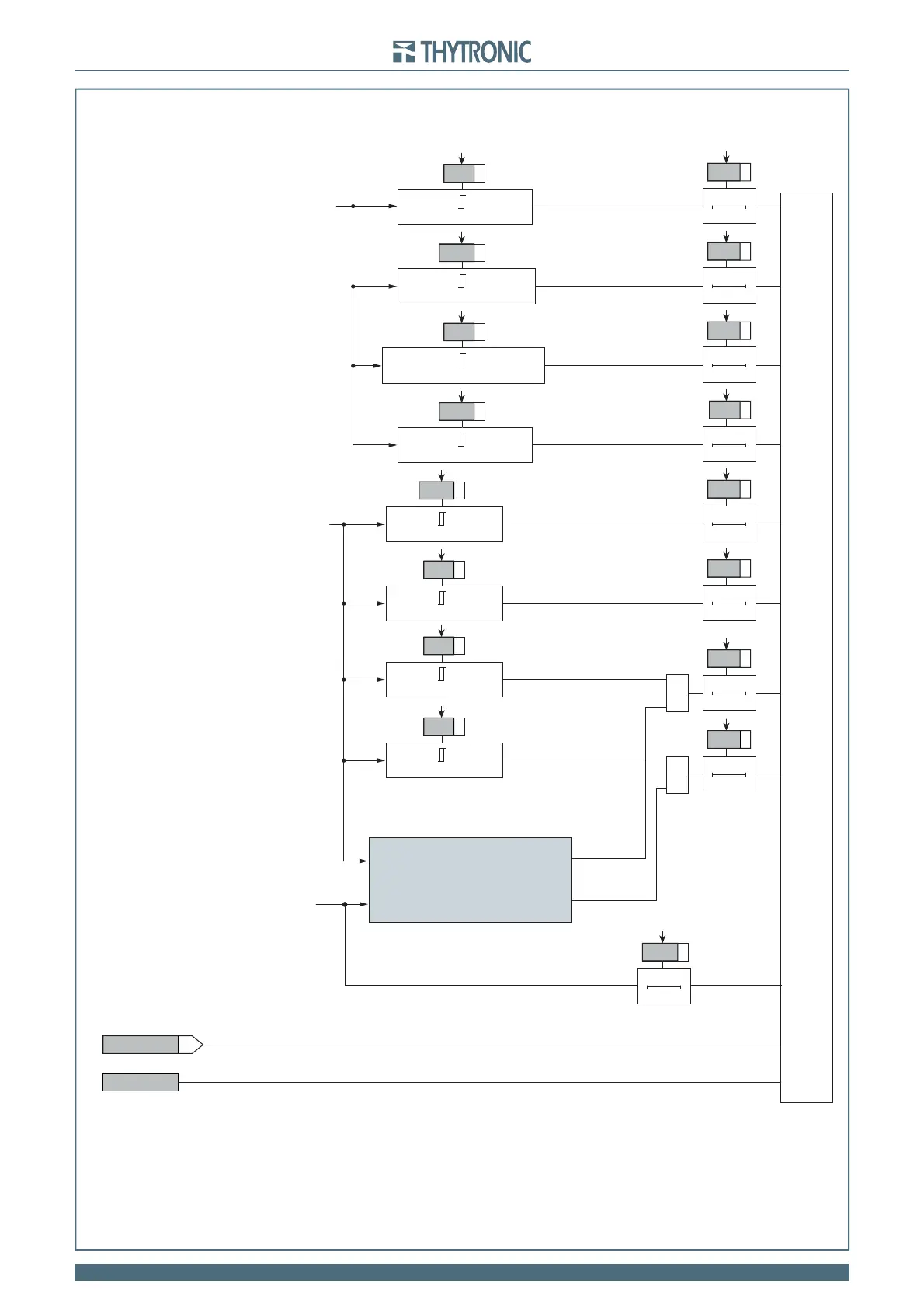
Logic diagram concerning the NV10P voltage control
t
U<def
0T
OPEN CB COMMAND
t
U<def
&
&
Remote trip
Binary input connected to remote trip external contact
Remote trip
Remote trip (Goose IEC61850)
U
12
ORU
23
ORU
31
<
U
<
def
U
<
def
t
U<<def
0T
t
U<<def
U
12
ORU
23
ORU
31
<
U
<<
def
U
<<
def
t
U
avg
>
0T
t
U
avg
>
U
12avg
ORU
23avg
ORU
31avg
≥
U
>
avg
U
>
avg
t
U>>def
0T
t
U>>def
U
12
ORU
23
ORU
31
≥
U
>>
def
t
f>def
0T
t
f>def
f ≥
f>
>
def
U
>>
def
f
>>
def
t
f<<def
0T
t
f<<def
f <
f
<<
def
f
<<
def
t
f>def
0T
t
f>def
f ≥
f>
def
f
>
def
t
f<def
0T
t
f<def
f <
f<
def
f
<
def
Trip U
E
>>
t
UE>>def
0T
t
UE>>def
81O-81U first threshold
enabling logic
(see following page)
f> Control
f< Control