56
56
NV10P - Manual - 01 - 2015
CHARACTERISTICS
Positive sequence undervoltage - 27V1
Preface
The protection has an adjustable threshold and defi nite time characteristic.
Enabling or disabling is provided by means ThySetter, the element can be temporarily blocked by
keyboard command.
Operation and settings
The positive sequence voltage is calculated as:
U
1
=(U
L1
+e
+j120°
·U
L2
+e
-j120°
·U
L3
)/3 where U
L1
, U
L2
and U
L3
are the phase-ground for versions with in-
puts from electronic sensors, or
U
1
=(U
12
+e
+j120°
·U
23
+e
-j120°
·U
31
)/3 where U
12
, U
23
e U
31
are the voltages for versions with in-
puts from inductive VTs phase-to-phase, or by direct measurement of line voltages and with
e
-j120°
=-1/2-j√3/2, e
j120°
=-1/2+j√3/2.
For versions with voltage inputs from phase to earth measurement, the thresholds are expressed
in pu E
n
, for versions with phase-to-phase inputs from inductive VTs or direct measurement, the
thresholds are expressed in pu U
n
.
The voltage of the positive sequence is compared with the threshold (U
1
<
def
).
A start is issued when the positive sequence voltage goes below adjustable threshold (START).
After expiry of the associated operate time (t
U1
<) a trip command is issued; if instead the voltages
exceed the threshold, the element is restored.
The element can be enabled or disabled by setting ON or OFF the State parameter inside the Set \
Profi le A(or B) \ Positive sequence undervoltage-27V1 \ U1< Element \ Defi nite time menu.
The user can disable the 27V1 protection by means of a keyboard command (DISABLE 27 FUNCTION
BY OPERATOR). During this command, the output trip relays (manual or automatic reset, normally
energized or de-energized) are forced to idle state, the “Disable 27-27V1” message is displayed “and
all the LEDs fl ash until the end of the command.
The element can be disabled in the case of connection of the measuring inputs (TV or TV-I-NI) down-
stream of the Device Interface when the DI is open.
The threshold disabling is selected by setting ON the U1<disbyCB_OPEN parameter, inside the
Set \ Profi le A(or B) \ Positive sequence undervoltage-27V1 \ U1< Element \ Setpoints menu.
Breaker failure (BF)
The undervoltage element can produce the Breaker Failure output if the U1< BF parameter is set
to ON. The parameter is available inside the Set \ Profi le A(or B) \ Positive sequence undervoltage
- 27V1 \ U1< Element \ Setpoints menu.
[1]
Note 1 The common settings concerning the Breaker failure protection are adjustable inside the Breaker Failure - BF menu.
U
1
U
1
<
t
t
U1
<
TRIP
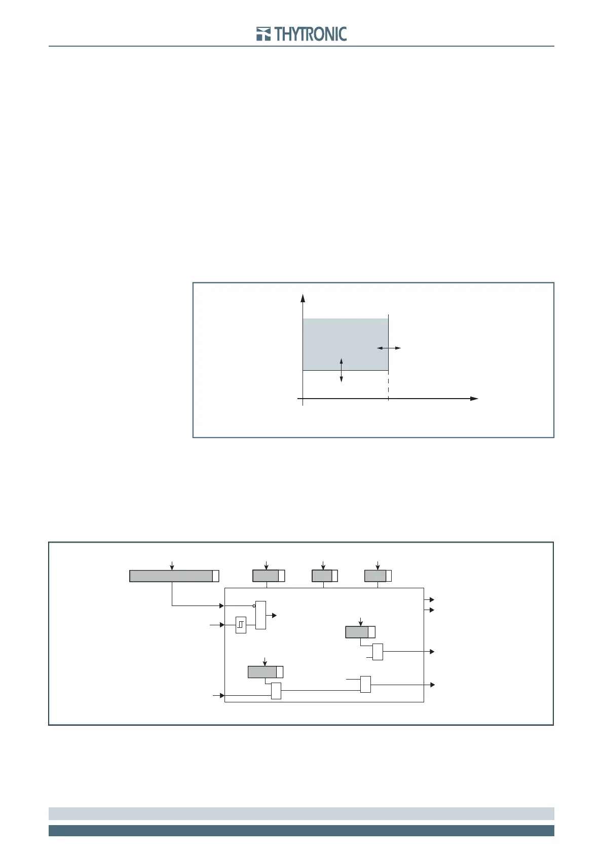
General operation time characteristic for the positive sequence undervoltage elements - 27V1
U
1
U
1
<
t
t
U1
<
TRIP
General operation time characteristic for the positive sequence undervoltage elements - 27V1
all-F27V1.ai
U1< Element
MMI
Start U1<
Trip U1<
t
U1<
def
U
1
<
def
State
Block1
BLK1U<
&
U1<BLK1
Start U1<
&
U1<BF
Trip U1<
&
U1<BF
&
U
1
Disable 27 functions by operator
General logic diagram of the positive sequence undervoltage elements - 27V1
all-F27V1.ai
U1< Element
MMI
Start U1<
Trip U1<
t
U1<
def
U
1
<
def
State
Block1
BLK1U<
&
U1<BLK1
Start U1<
&
U1<BF
Trip U1<
&
U1<BF
&
U
1
Disable 27 functions by operator
General logic diagram of the positive sequence undervoltage elements - 27V1