71
NV10P - Manual - 01 - 2015
CHARACTERISTICS
Overfrequency - 81O
Preface
Two operation thresholds, independently adjustable (f>, f>>) with adjustable delay (t
f
>, t
f
>>) are
provided.
Each threshold may be separately enabled or disabled.
The fi rst threshold trip (f >) may be inhibited by start of the second threshold (f >>).
Operation and settings
The frequency, acquired from U
L1
,
U
L2
,
U
L3
input voltages
[1]
is compared with the setting values (f>,
f>>); a start is issued when the frequency overcomes the adjustable threshold (START); after expiry
of the associated operate time (t
f
>, t
f
>>) a trip command is issued; if instead the frequency drops
below the threshold, the element is restored.
When the frequency value is out of the lock range, it is fi xed to the upper or lower limit
(20 Hz or 90 Hz).
Both elements operate with defi nite time characteristic.
Each element can be enabled or disabled by setting ON or OFF the State parameter inside the Set
\ Profi le A(or B) \ Overfrequency-81O \ f> Element (or f>> Element \ Defi nite time menu.
The overfrequency protection is enabled only when the maximum of the input voltages
U
LMAX
=max(U
L1
, U
L2
, U
L3
) overcomes 0.2 U
n
for a tfEN adjustable time.
Setting of the tfEN value is available inside the Set \ Base menu with “level 1” session.
The fi rst threshold trip (f >) may be inhibited by start of the second threshold (f>>) by setting ON the
f> Disabling by f>> start (f>disbyf>>) parameter available inside the Set \ Profi le A(or B) \ Overfre-
quency-81O \ f>> Element \ Setpoints menu.
The elements can be disabled in the case of connection of the measuring inputs (TV or TV-I-NI)
downstream of the Device Interface when the DI is open. The threshold disabling is selected by set-
ting ON the f>disbyCB_OPEN, f>>disbyCB_OPEN parameters, inside theSet \ Profi le A(or B) \
Overfrequency-81O \ Setpoints menu.
Note 1 For sensors inputs versions the frequency is measured on the phase voltages (U
L1
, U
L2
, U
L3
), while for versions with inductive VTs inputs the
frequency is measured on-phase-to-phase voltages (U
12
, U
23
, U
31
).
On the diagrams U
L1
, U
L2
, U
L3
are the input phase voltages or phase-to-phase according to the corresponding versions
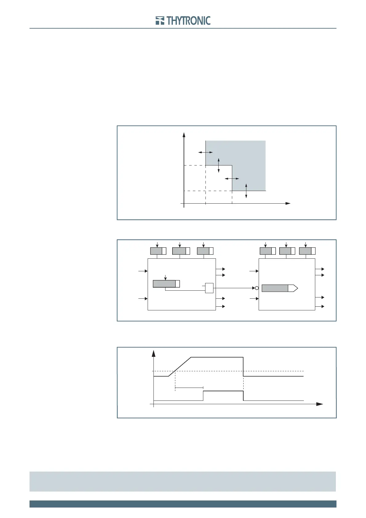
t-int-F81O.ai
f
t
General operation time characteristic for the overfrequency elements - 81O
f >>
def
f >
def
t
f
def>>
t
f
def>
TRIP
t-int-F81O.ai
f
t
General operation time characteristic for the overfrequency elements - 81O
f >>
def
f >
def
t
f
def>>
t
f
def>
TRIP
Logic diagram concerning the overfrequency elements - 81O
all-F81O.ai
f
UL1,
f
UL2,
f
UL3
f
UL1,
f
UL2,
f
UL3
ON=inhibit
2nd Element 1st Element
Block1
Block1
Block1
BF
&
Block1
BF
State
f>disbyf>>
f
>
def
t
f>def
State
f
>>
def
t
f>>def
f> inhibition
f
> Start
f
> Trip
f
>> Start
f
>> Start
f
>> Trip
Timers-F81.ai
t
dfEN
81O-81U Enable
81O-81U disabled 81O-81U disabled81O-81U enabled
0.20 U
n
Max (U
L1
...U
L3
)
t
Overfrequency & underfrequency enable timer
Timers-F81.ai
t
dfEN
81O-81U Enable
81O-81U disabled 81O-81U disabled81O-81U enabled
0.20 U
n
Max (U
L1
...U
L3
)
t
Overfrequency & underfrequency enable timer