72
72
NV10P - Manual - 01 - 2015
CHARACTERISTICS
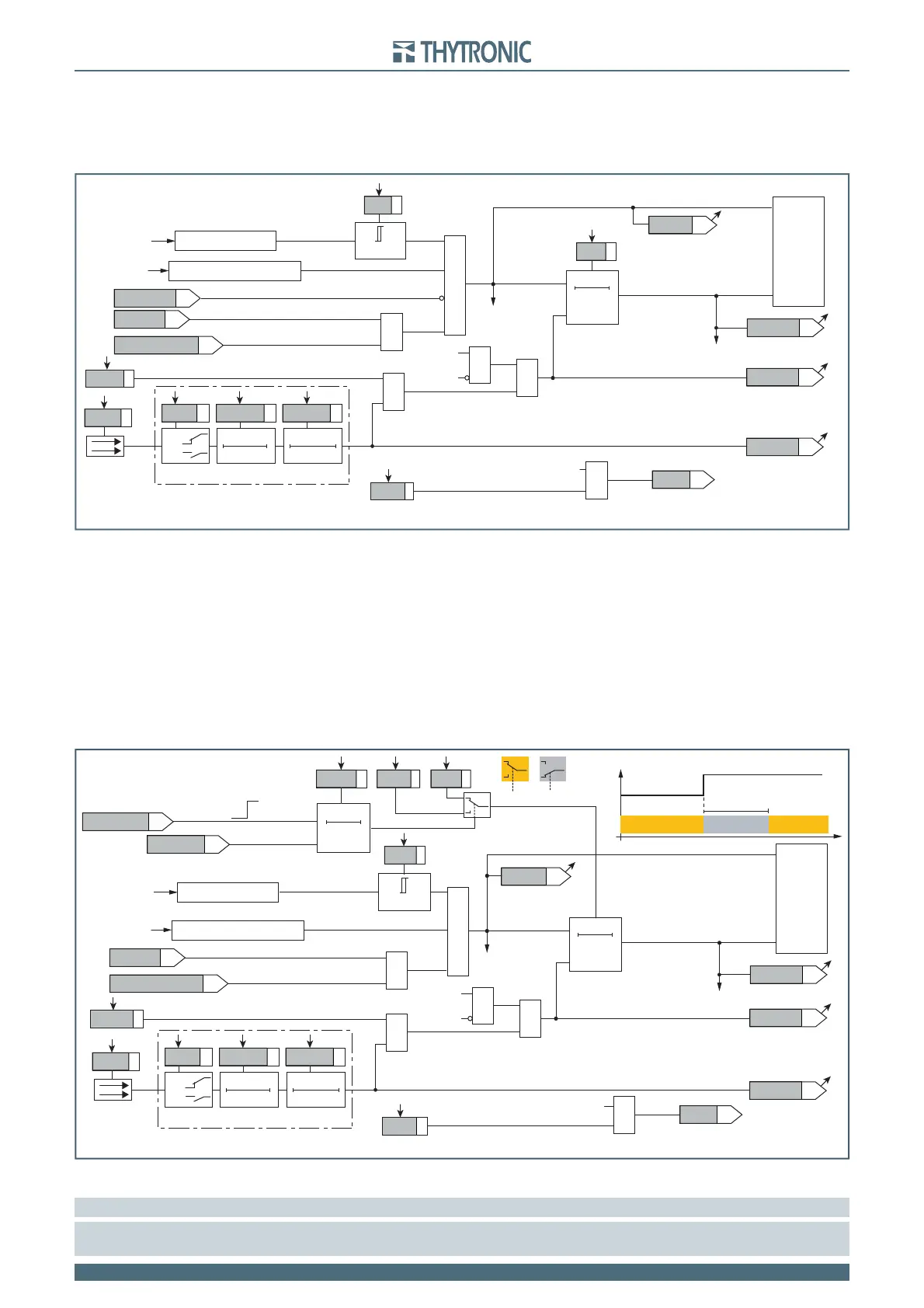
When the CB closes, the operate time of the f>> element is automatically adjusted to a reduced
value tcf>>def for an adjustable time tatcf>>def. The reduction of the operate time for the sec-
ond threshold can be selected by setting the EnTcf>>def parameter inside the Set \Profi le A(or B)
\ Overfrequency-81O \ f>> Element \ Setpoints menu, while the timers are adjustable inside the Set
\Profi le A(or B) \ Overfrequency-81O \ f>> Element \ Defi nite time menu.
Breaker failure (BF)
Both overfrequency elements (f>, f>>) can produce the Breaker Failure output if the f>BF and
f>>BF parameters are set to ON.
The parameters are available inside the Set \ Profi le A(or B) \ Overfrequency - 81O \ f> Element (f>>
Element) \ Setpoints menus.
[1]
Logical block (Block1)
If the f>BLK1 and/or f>>BLK1 enabling parameters are set to ON and a binary input is designed
for logical block (Block1), the protection is blocked off whenever the given input is active.
The trip timer is held in reset condition, so the operate time counting starts when the input block goes
down.
[2]
The enabling parameters are available inside the Set \ Profi le A(or B) \ Overfrequency - 81O
\ f> Element (f>> Element) \ Setpoints menus, while the Block1 function must be assigned to the
selected binary input inside the Set \ Inputs \ Binary input IN1(x2) menus (IN1 or INx matching).
Note 1 The common settings concerning the Breaker failure protection are adjustable inside the Breaker Failure - BF menu.
Note 2 The exhaustive treatment of the logical block (Block 1) function may be found in the “Logic Block” paragraph inside CONTROL AND MONITOR-
ING section.
Logic diagram concerning the first threshold (f>) of the overfrequency element - 81O
Fun-F81O_S1-cei.ai
f>
inhibition
(ON≡
Inhibit
)
&
RESET
t
f>
0T
TRIPPING MATRIX
(LED+RELAYS)
t
f>def
f>
Start
f>
Start
f>
Trip
f>
Trip
f>
Block1
f>
Trip
BF Enable (ON≡Enable)
f>BF
towards BF logic
&
f>
BF
&
&
&
Enable (ON≡Enable)
Block1 input (ON≡Block)
Block1
Block1
f
≥
f
>
def
f
>
def
U
L1
,U
L2
,U
L3
Max(U
L1...
U
L3
) ≥20%U
n
Binary input INx
T0
Logic
INx
t
ON
INx
t
ON
INx
t
OFF
T0
n.o.
n.c.
INx
t
OFF
f>
ST-K
f>
ST-L
f>
TR-K
f>
TR-L
f>BLK1
≥1
(1≡DDI closed)
DDI state
(1≡upstream)
f>disbyCB_OPEN
Max(f
UL1,
f
UL2,
f
UL3
)
f
UL1,
f
UL2,
f
UL3
Logic diagram concerning the second threshold (f>>) of the overfrequency element - 81O
Fun-F81O_S2-cei.ai
&
RESET
t
f>>
0T
TRIPPING MATRIX
(LED+RELAYS)
f>>
Start
f>>
Start
f>>
Trip
f>>
Trip
f>>
Block1
f>>
Trip
BF Enable (ON≡Enable)
f>>BF
towards BF logic
&
f>>
BF
&
&
&
Enable (ON≡Enable)
Block1 input (ON≡Block)
Block1
Block1
f
≥
f
>>
def
f
>>
def
U
L1
,U
L2
,U
L3
Max(U
L1...
U
L3
) ≥20%U
n
Binary input INx
T0
Logic
INx
t
ON
INx
t
ON
INx
t
OFF
T0
n.o.
n.c.
INx
t
OFF
f>>
ST-K
f>>
ST-L
f>>
TR-K
f>>
TR-L
f>>BLK1
(closing)
DDI OFF->ON
(1≡upstream)
EnTcf>>def
t
atcf>>def
0T
RESET
t
f>>def
t
cf>>def
t
atcf>>def
“1”
“0”
TV downstream
CB State
CB CLOSED (52a=ON)
CB OPEN (52a=OFF)
t
f>>
=
t
cf>>def
t
f>>
=
t
cf>>def
t
atcf>>def
t
f>>
t
f>>
=
t
f>>def
≥1
(1≡DDI closed)
DDI state
(1≡upstream)
f>>disbyCB_OPEN
Max(f
UL1,
f
UL2,
f
UL3
)
f
UL1,
f
UL2,
f
UL3