73
NV10P - Manual - 01 - 2015
CHARACTERISTICS
Underfrequency - 81U
Preface
Four operation thresholds, independently adjustable with adjustable delay are provided.
Each threshold may be separately enabled or disabled.
Operation and settings
The frequency, acquired from U
L1
,
U
L2
,
U
L3
input voltages
[1]
is compared with the setting thresholds;
a start is issued when the frequency goes down the adjustable threshold (START); after expiry of the
associated operate time a trip command is issued; if instead the frequency goes over the threshold,
the element is restored.
All elements operate with defi nite time characteristic.
When the frequency value is out of the lock range, it is fi xed to the upper or lower limit
(20 Hz or 90 Hz).
All elements operate with defi nite time characteristic.
Each element can be enabled or disabled by setting ON or OFF the State parameter inside the Set \
Profi le A(or B) \ Underfrequency-81U \ f< Element (f<< Element, f<<< Element, f<<<< Element) \ Defi -
nite time menu.
Note 1 For sensors inputs versions the frequency is measured on the phase voltages (U
L1
, U
L2
, U
L3
), while for versions with inductive VTs inputs the
frequency is measured on-phase-to-phase voltages (U
12
, U
23
, U
31
).
On the diagrams U
L1
, U
L2
, U
L3
are the input phase voltages or phase-to-phase according to the corresponding versions
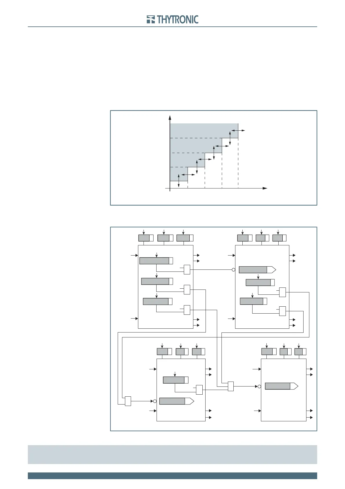
General operation time characteristic for the underfrequency elements - 81U
f
f<<<<
def
f<<<
def
f
<<
def
f<
def
t
t
f
def
<<
t
f
def
<<<
t
f
def
<<<<
t
f
def
<
TRIP
General operation time characteristic for the underfrequency elements - 81U
f
f<<<<
def
f<<<
def
f
<<
def
f<
def
t
t
f
def
<<
t
f
def
<<<
t
f
def
<<<<
t
f
def
<
TRIP
Logic diagram concerning the underfrequency elements - 81U
all-F81U.ai
4th Pickup Element
Block1
Block1
BF
State
f
<<<<
t
f
<<<<
&
f
<<< Start
f
<<<< Start
f
<<<< Start
f
<<<< Start
&
&
f
<<< Trip
≥
≥
3rd Pickup Element
Block1
Block1
BF
State
f
<<<
t
f
<<<
&
f
<<< Start
f
<<< Start
&
f
<<< Start
f
<<< Trip
ON=inhibit
ON=inhibit
ON=inhibit
2nd Pickup Element
Block1
Block1
BF
1st Pickup Element
Block1
Block1
BF
State State
f
<<
t
f
<<
&
f< inhibition
f<< inhibition
f
<< Start
f
<< Start
f
<< Trip
f
<
t
f
<
f
< Start
f
< Trip
f<<< inhibition
f<disbyf<<
f<disbyf<<<<
f<<disbyf<<<<
f<<disbyf<<<
f<disbyf<<<
f<<<disbyf<<<<
f
UL1,
f
UL2,
f
UL3
f
UL1,
f
UL2,
f
UL3
f
UL1,
f
UL2,
f
UL3
f
UL1,
f
UL2,
f
UL3