64
64
NV10P - Manual - 01 - 2015
CHARACTERISTICS
Residual overvoltage - 59N
Preface
Two operation thresholds, independently adjustable (U
E
>, U
E
>>) with adjustable delay (t
UE
>, t
UE
>>).
The fundamental component of the residual voltage is computed, therefore the element is insensitive
to the third harmonic components.
The fi rst threshold (U
E
>) can be programmed with defi nite or inverse time, while the second thresh-
old operates with defi nite time characteristic.
Each threshold may be separately enabled or disabled.
The fi rst threshold trip (U
E
>) may be inhibited by start of the second threshold (U
E
>>).
Operation and settings
With VTs input version two measuring criteria of the residual voltage are provided:
Direct
Calculated.
while for versions with inputs from sensors the residual voltage is always calculated.
For direct measure the fundamental component of the residual voltage input is used (U
E
), whereas,
for calculated measure (U
EC
) the residual voltage comes from a vector sum of three phase voltage
phasors.
The residual voltage (U
E
or U
EC
) is compared with the setting values (U
E
>, U
E
>>); a start is issued
when the residual voltage overcomes the adjustable threshold (START); after expiry of the associ-
ated operate time (t
UE
>, t
UE
>>) a trip command is issued; if instead the voltage drops below the
threshold, the element is restored.
The fi rst threshold (U
E
>) may be programmed with defi nite or inverse time according the following
characteristic curve:
t=0.5 t
UE
>
inv
/ [(U
E
/U
E
>
inv
) - 1] or
t=0.5 t
UE
>
inv
/ [(U
EC
/U
E
>
inv
) - 1]
Where:
U
E
: measured residual voltage
U
EC
: calculated residual voltage
t: operate time
U
E
>
inv
: pickup value
t
UE>inv
: operate time setting
For the inverse time characteristic, following data applies:
The operate time setting is referred to an input voltage equal to 1.5 of the pickup value.
Asymptotic reference value (minimum pickup value): 1.1 U
E
>
inv
Minimum operate time: 0.1 s
Range where the equation is valid: 1.1 ≤ U
E
/U
E
>
inv
(U
EC
/U
E
>
inv
) ≤ 4
If U
E
>
inv
pickup ≥ 0.5 U
En
, the upper limit is 2 U
En
.
The fi rst residual overvoltage element can be programmed with defi nite or inverse time character-
istic by setting the UE> Curve parameter (DEFINITE, INVERSE) available inside the Set \ Profi le
A(or B) \ Residual overvoltage-59N \ UE> Element \ Setpoints menu.
For defi nite time characteristic the upper limit is 2 U
En
.
Each element can be enabled or disabled by setting ON or OFF the UE> Enable parameter inside
the Set \ Profi le A(or B) \ Residual overvoltage-59N \ UE> Element \ Setpoints menu and/or the State
parameter inside the Set\Profi le A(or B) \ Residual overvoltage-59N \ UE>> Element \ Defi nite time.
Selection of the measuring criteria of the residual voltage (direct measure or calculated measure) is
available inside the Set \ Profi le A(or B) \ Residual overvoltage-59N \ Common confi guration menu;
The 3Votype59N parameter may be select as UE (direct measure) or UEC (calculated measure).
•
•
•
•
•
•
•
U
EC
=|U
L1
+U
L2
+U
L3
|U
EC
=|U
L1
+U
L2
+U
L3
|
U
E
U
E
>>
t
UE
>
t
UE
>>
U
E
>
t
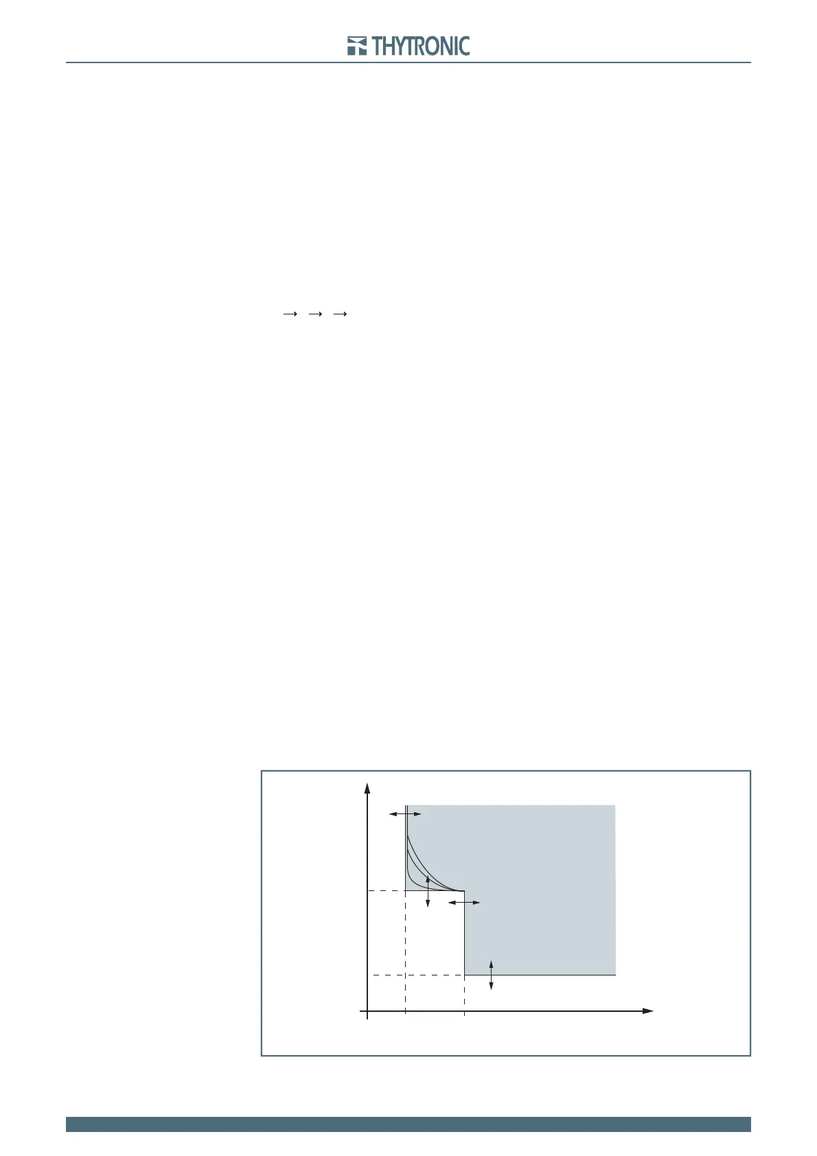
General operation time characteristic for the residual overvoltage elements - 59N
TRIP
U
E
U
E
>>
t
UE
>
t
UE
>>
U
E
>
t
General operation time characteristic for the residual overvoltage elements - 59N
TRIP