65
NV10P - Manual - 01 - 2015
CHARACTERISTICS
With UE setting (direct voltage measurement), the thresholds are in p.u. U
En
, with UEC setting (cal-
culated voltage measurement), the thresholds are in p.u. U
ECn
.
For both measuring criteria, a block of the U
E
> and U
E
>> threshold may be select when the 74VT
function is active (external by binary input). The blocking enabling parameter 74VText59N is avail-
able inside the Set \ Profi le A(or B) \ Residual overvoltage-59N \ Common confi guration menu.
[1]
The fi rst threshold trip (U
E
>) may be inhibited by start of the second threshold (U
E
>>) by setting ON
the UE> Disabling by UE>> start (UE>disbyUE>>) parameter available inside the Set \ Profi le
A(or B) \ Residual overvoltage-59N \ UE>> Element \ Setpoints menu.
The elements can be disabled in the case of connection of the measuring inputs (TV or TV-I-NI)
downstream of the Device Interface when the DI is open.
The threshold disabling is selected by setting ON the UE>disbyCB_OPEN, UE>>disbyCB_
OPEN parameters, inside the Set \ Profi le A(or B) \ Residual overvoltage-59N \ UE> Element (UE>>
Element) \ Setpoints menu.
When the CB closes, the operate time of the UE >> element is automatically adjusted to a reduced
value tcUE>>def for an adjustable time tatcUE>>def. The reduction of the operate time for the
second threshold can be selected by setting the EnTcUE>>def parameter inside the Set \Profi le
A(or B) \ Residual overvoltage-59N \ UE>> Element \ Setpoints menu, while the timers are adjustable
inside the Set \Profi le A(or B) \ Residual overvoltage-59N \ UE>> Element \ Defi nite time menu.
An adjustable reset time delay is provided for every threshold t
UE>RES
, t
UE>>RES
.
Breaker failure (BF)
Both residual overvoltage elements (U
E
>, U
E
>>) can produce the Breaker Failure output if the
UE>BF and UE>>BF parameters are set to ON.
The parameters are available inside the Set \ Profi le A(or B)\Residual overvoltage - 59N \ UE> Element
(UE>> Element) \ Setpoints menus.
[2]
Note 1 The operating time must be adjusted to a greater value than the 74VT activation time (internal or binary input)
Note 2 The common settings concerning the Breaker failure protection are adjustable inside the Breaker Failure - BF menu.
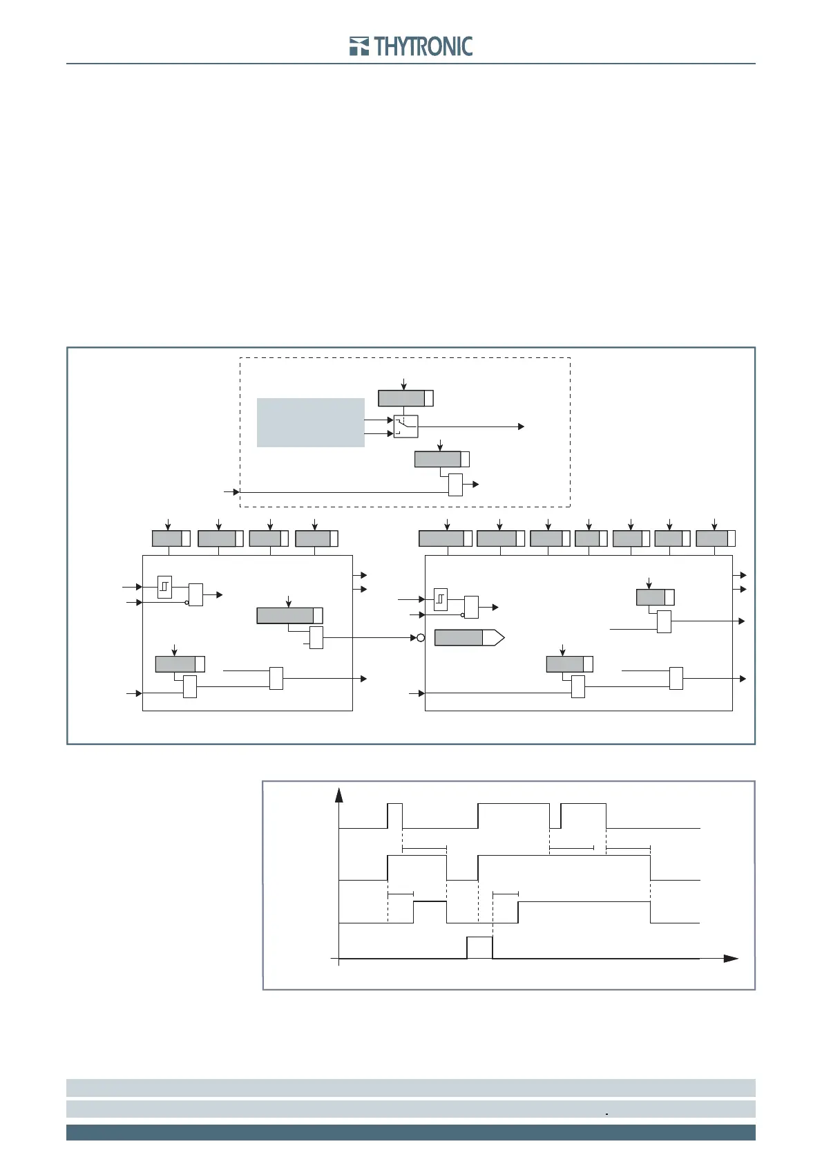
Logic diagram concerning the residual overvoltage element - 59N
all-F59N.ai
U
E
UE> Element
UE>> Element
Start U>>
Start UE>> Start UE>
Trip UE>Trip UE>>
&
UE> disbyUE>>
U> inhibition
t
UE>
def
t
UE>
inv
UE>
def
t
UE>>
def
t
UE>>RES
t
UE>RES
UE>>
def
UE>
inv
UE> CurveUE> EnableState
Block1
BLK1UE>
&
UE>BLK1
Start UE>
&
Block1
BLK1UE>>
&
UE>>BLK1
Start UE>>
&
UE>BF
Trip UE>
&
UE>BF
&
U
E
&
74VText-Block
74VText-Block
74VText-Block
&
74VText
U
E
(misura diretta)
U
EC
(misura calcolata)
U
E
Common configuration
3Votype59 N
74VText59 N
Only with TV versions
Timers-F59N.ai
UE> Start
UE> Trip
t
UE>
t
UE>
RESET
INPUT
t
UE>RES
t
UE>RES
t
UE>RES
t
Timers concerning the first element of residual overvoltage protection- 59N
Timers-F59N.ai
UE> Start
UE> Trip
t
UE>
t
UE>
RESET
INPUT
t
UE>RES
t
UE>RES
t
UE>RES
t
Timers concerning the first element of residual overvoltage protection- 59N