100
100
NV10P - Manual - 01 - 2015
CHARACTERISTICS
Oscillography
Trigger Setup
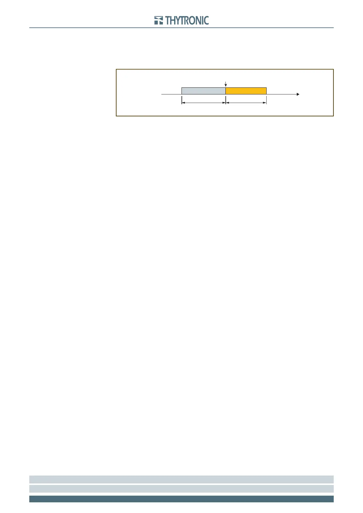
Following parameters, available inside the Set \ Oscillography \ Trigger Setup menu, are user-pro-
grammable:
Pre-trigger time and Post-trigger time.
Element pickup trigger; the information recording starts when a state transition on any protec-
tive element occurs if the parameter is set to ON.
Trigger from outputs; the information recording starts when a state transition on the selected
output relay occurs if the parameter is set (K1...K6).
Binary input trigger; the information recording starts when a state transition on the selected
binary input occurs if the parameter is set to ON.
Trigger from inputs; the information recording starts when a state transition on the selected
binary input occurs if the parameter is set (IN1...INx).
80% Buffer alarm; when the 80% of the buffer space is reached an alarm may be issued if the
parameter is set to ON.
Set sampled channels
The desired sampled quantities may be select inside the Set \ Oscillography \ Set sampled channels
menu (u
L1
, u
L2
, u
L3
, u
E
).
Set analog channels
The desired sampled quantities may be select inside the Set \ Oscillography \ Set analog channels
menu.
Everyone of twelve analog channel may be associated to one of the selected measures (f
UL1
, f
UL2
,
f
UL3
, U
L1
, U
L2
, U
L3
, U
12
, U
23
, U
31
, U
E
, U
EC
, U
1
, U
2
, df/dt,, T1...T8
[1]
).
Set digital channels
The desired digital quantities may be select inside the Set \ Oscillography \ Set digital channels
menu.
Everyone of twelve digital channel may be associated to one of the selected I/O signal (K1... K6, K7...
K10, IN1, IN2, IN3...IN42
[2]
).
Note 1 The 26 menu is available when the MPT module is enabled
Nota 2 The output relay K7...K10 and binary input IN3...IN42 states is meaningful when the I/O circuits are present (MRI and MID16 modules)
•
•
•
•
•
•
trigger.ai
Trigger oscillography
Trigger
Time
pre-trigger post-trigger