103
NV10P - Manual - 01 - 2015
MEASURES, LOGIC STATES AND COUNTERS
Twenty events are recorded into a circular FIFO (First In, First Out) buffer.
[1][2]
Following information are stored in every record:
Fault counter
[3]
Date and time
Fault cause (element trip)
Input phase voltages U
L1r
, U
L2r
, U
L3r
Input phase-to-phase voltages U
12r
, U
23r
, U
31r
Phase average voltages U
L1avgr
, U
L2avgr
, U
L3avgr
Phase-to-phase average voltages U
12avgr
, U
23avgr
, U
31avgr
Measured residual voltage U
Er
Calculated residual voltage U
ECr
Positive sequence voltage U
1r
Negative sequence voltage U
2r
Frequency f
UL1r
, f
UL2r
, f
UL3r
Frequency rate of change df
r
Inputs IN1-IN2-...
Outputs K1-K6
Fault cause info (eg. faulted phase)
Event recording - SER
Recording is triggered by one or more causes:
Start and/or trip of any enabled protection or control element
Binary input activation (OFF-ON or ON-OFF transition)
Power-on or power-down (Auxiliary power supply)
Setting change.
Three hundred events are recorded into a circular FIFO (First In, First Out) buffer.
[2][4]
Following information are stored in every record:
Event counter
[5]
Date and time
Event cause (binary input/element trip/setting change)
Oscillography - DFR
Upon programmable trigger, the fault records are recorded in COMTRADE format; the sampled mea-
sures (24 sample per cycle) are stored in a circular shift memory buffer.
The fault record are self-triggered; they are stored in sequential order up the allocated memory is
used up after which the oldest memory is overwritten.
An operating procedure example for the digital fault recording is illustrated inside the ThySetter
section.
Following parameters are user-programmable:
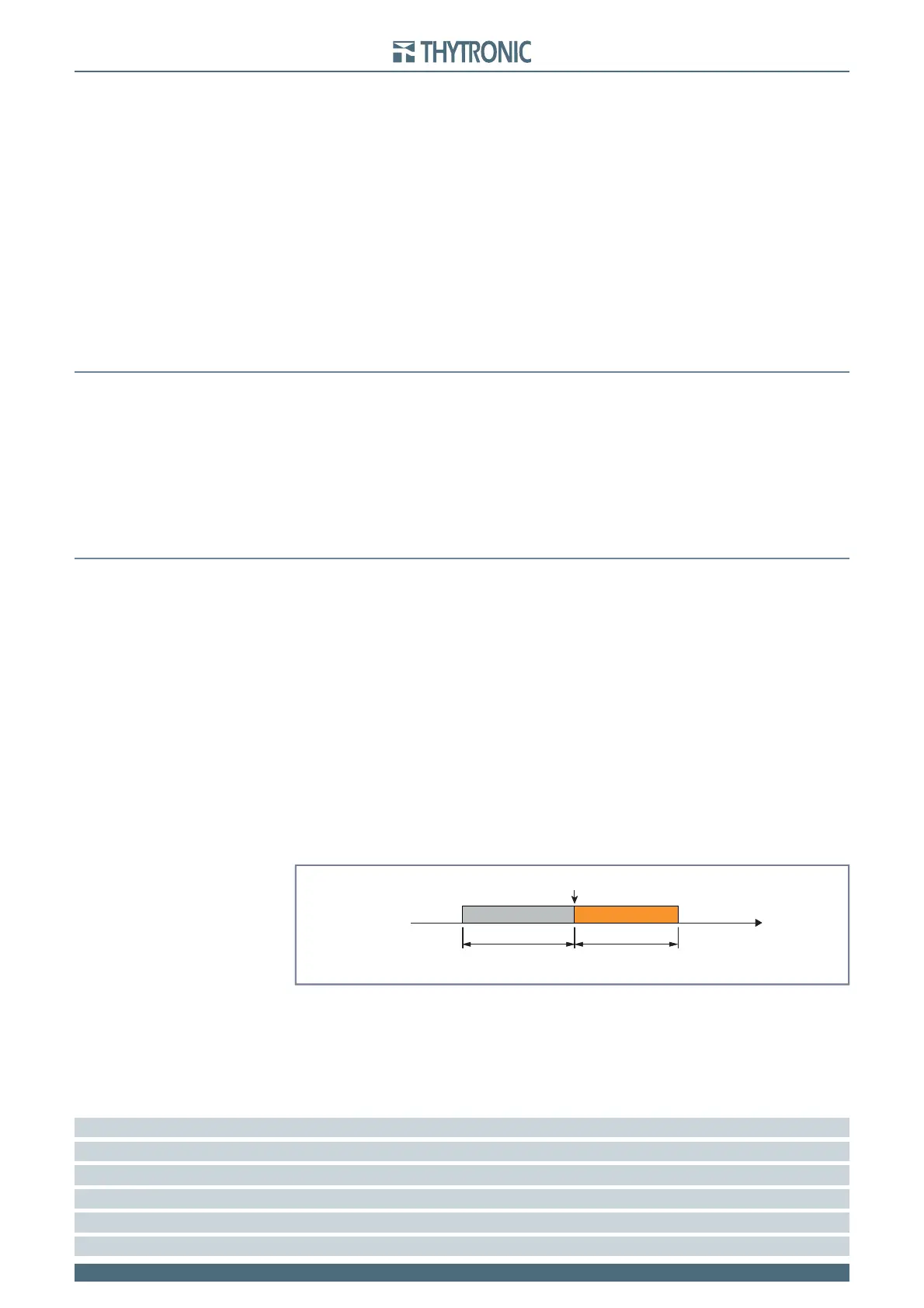
Pre-trigger and post-trigger time
Selected sampled quantities.
Analog channels (1...12) allocation.
Digital channels (1...12) allocation (output relay and/or binary inputs).
Trigger setup; the information storage starts when a state transition on the selected signal occurs.
(protective element start and/or trip, output relay and/or binary input switching).
Alarm: when the 80% of the buffer space is reached an alarm may be issued. The system being
of linear type, the records are back-to-back recorded to the end of available memory; the alarm
output is a warning in order that the user may download the data FLASH
[6]
to clear memory for
new records.
Following parameters are user-programmable:
Sample channels
Instantaneous value for input voltages u
L1
, u
L2
, u
L3
Instantaneous value for residual voltage u
E
Note 1 Fault 0 is the newest fault, while the Fault 19 is the oldest fault
Note 2 Data are stored in non volatile memory; they are held in spite of power down
Note 3 Counter is updated at any new record; it may be cleared by means ThySetter
Note 4 Event 0 is the newest event, while the Event 299 is the oldest event
Note 5 Counter is updated at any new record; it may be cleared by means ThySetter
Note 3 Data are stored into non volatile memory FLASH, they are preserved also when power goes down
•
•
•
•
•
•
•
•
•
•
•
•
•
•
•
•
•
•
•
•
•
•
•
•
•
•
•
•
•
•
•
trigger.ai
Trigger oscillography
Trigger
Time
pre-trigger post-trigger
trigger.ai
Trigger oscillography
Trigger
Time
pre-trigger post-trigger