8
8
NV10P - Manual - 01 - 2015
INTRODUCTION
Symbols-en.ai
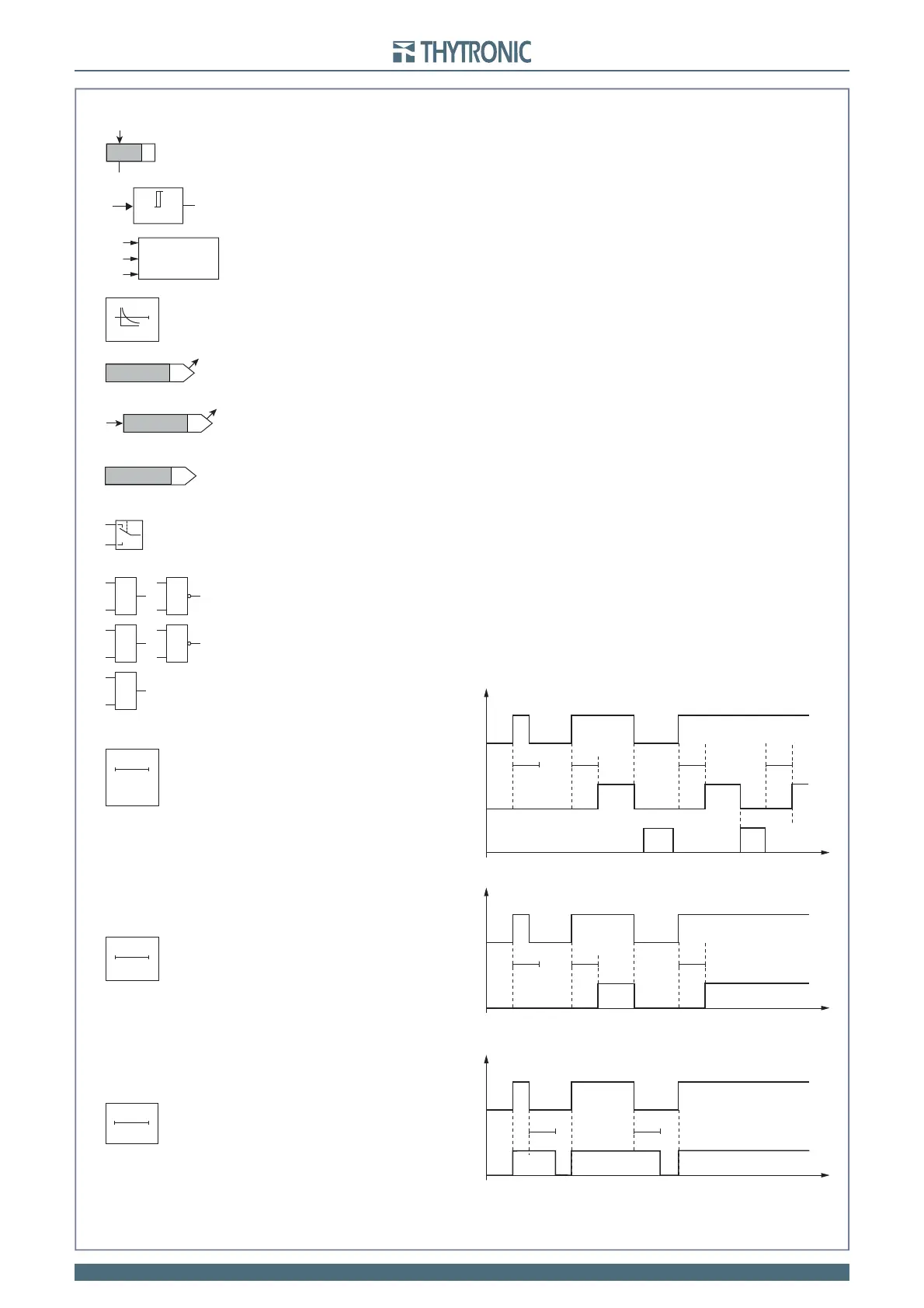
Symbols
U>> Start
U>> BF_OUT
IPh Block2
Logic internal signal (output); may be a logical state
(e.g.U>> Start
) or a numerical value
It is available for reading (ThySetter + communication interface)
Logic external signal (intput); may be a command coming from a binary input or a sw command
It is available for reading (ThySetter + communication interface)
Internal signal (e.g. Breaker Failure output state concerning to the 2nd threshold of the 59 element)
It is not available for reading (missing arrow)
AND and NAND logic gates
OR and NOR logic gates
Limit block (U>> threshold).
Computation block (Max phase voltage)
Threshold setting (e.g. pickup
U >>)
.
The value is available for reading and is adjustable by means ThySetter + MMI.
Switch
ON delay timer with reset (
t
ON
delay)
ON delay timer without reset (
t
ON
delay)
OFF delay timer (dropout) without reset (t
OFF
delay)
Curve type (definite/inverse time)
0T
U
L3
Max[I
L1
,I
L2
,I
L3
]
U
L2
U
L1
t
ON
t
ON
t
ON
t
ON
t
RESET
INPUT
OUTPUT
t
OFF
t
t
OFF
INPUT
OUTPUT
t
ON
t
ON
t
ON
t
INPUT
OUTPUT
0T
t
ON
& &
≥1 ≥1
EXOR logic gate
t
OFF
=1
U>>
U
U ≥
U >>
t
ON
RESET
0T
0T