77
NV10P - Manual - 01 - 2015
CHARACTERISTICS
Application notes about over-under frequency elements - 81U and 81O
To ensure compliance with CEI 0-16 italian standard the voltage enabling function is provided
through which the fi rst threshold can be enable / disable, respectively, in the absence / presence of
the signal integrity of the communication network Distributor (digital input set with inverse logic and
f <-f> Control function or communication interface protocol IEC 61850).
For the trip of the fi rst threshold of each element can be enabled by one or more of the following
consensus:
start of residual current second threshold (59N internal element by programming ON the f<&UE>>,
f>&UE>> parameter)
start of residual voltage second threshold (59N external element) acquired by means of binary input
programmed as f<-f> Control (setting ON the f<&DIGIN, f>&DIGIN parameter)
loss of communication network acquired by means of binary input programmed as f<-f> Control
with inverse logic (setting ON the f<&DIGIN, f>&DIGIN parameter)
start of positive sequence undervoltage threshold (27V1 programming ON the f<&27V1, f>&27V1
parameter)
start of negative sequence overvoltage threshold (59V2 programming ON the 59V2 (programming
ON the f<&59V2, f>&59V2 parameter)
start of fi rst threshold of the undervoltage element (27 programming ON the f<&U<, f>&U<
parameter)
loss of communication network from Goose IEC 61850 message programming ON the
f<&rete61850-KO, f>&rete61850-KO parameter.
The parameters listed above are available in the menus inside the menu
Set \ Profi le A(or B) \ Underfrequency - 81U \ f< element \ Voltage control for parameters concern-
ing to the underfrequency element (81U) and within the Set \ Profi le A(or B) \ Overfrequency - 81O \
f> element \ Voltage control menu for parameters concerning to the overfrequency element (81O).
•
•
•
•
•
•
•
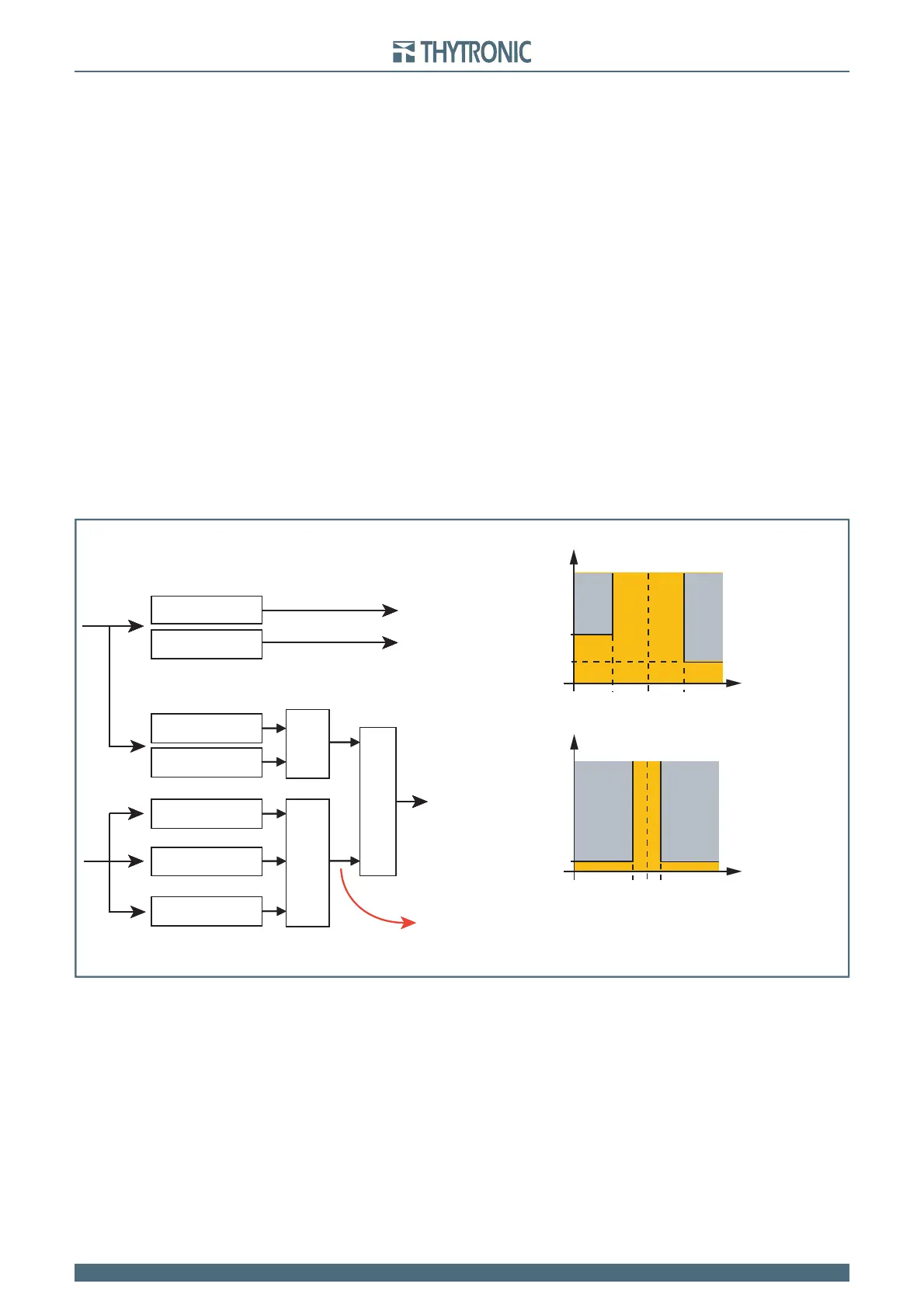
Operating logic for thresholds activation with voltmetric control
Delayed trip 4.0 s
Delayed trip 1.0 s
Delayed trip 0.1 s
ON = Fault (Start 59N and/or 27V1 and/or 59V2 element)
or
&
or
f (Hz)
without fault
f (Hz)
50
81>
81<
t (s)
restrictive thresholds
0.1
49.7 50.3
with fault
t (s)
permissive thresholds
f (Hz)
5047.5
1.0
4.0
51.5
81>>
81<<