39
NV10P - Manual - 01 - 2015
CHARACTERISTICS
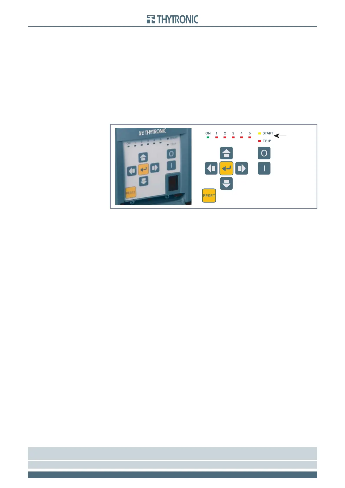
LED indicators
Eight LEDs are available.
One green LED “ON”: if turned on it means that the device is properly working, if fl ashing the inter-
nal self-test function has detected an anomaly.
One yellow LED “START” tagged for START of one or more protective elements.
[1]
One red LED “TRIP” tagged for TRIP of one or more protective elements.
[1]
Five red LEDs “1...5” for highlight the activation of one or more user defi ned function.
Each output relay may be programmed with following operating mode:
No-latched: the LED reset at the end of the trip condition.
Latched: the LED doesn’t reset at the end of the trip condition; it stays ON until a manual reset com-
mand is issued (RESET key, ThySetter or communication command).
Any change to the settings can be affected at any time, also with the relay on duty, separately for
each LED
Programming and/or confi guration changes can be carried out at any time, separately for each LED
by setting the parameters inside the Set\Led menu.
Free allocation of each LED may be set according to the matrix structure shown in the following
page.
[2]
Note 1 The START and the TRIP LED are user assignable to any function; other than starting and tripping information can be assigned to them too, just
the same for L1...L5
Note 2 All LEDs are unassigned in the default setting.
•
•
•
•
•
•
LEDsLEDs