6
6
NV10P - Manual - 01 - 2015
INTRODUCTION
Product identifi cation
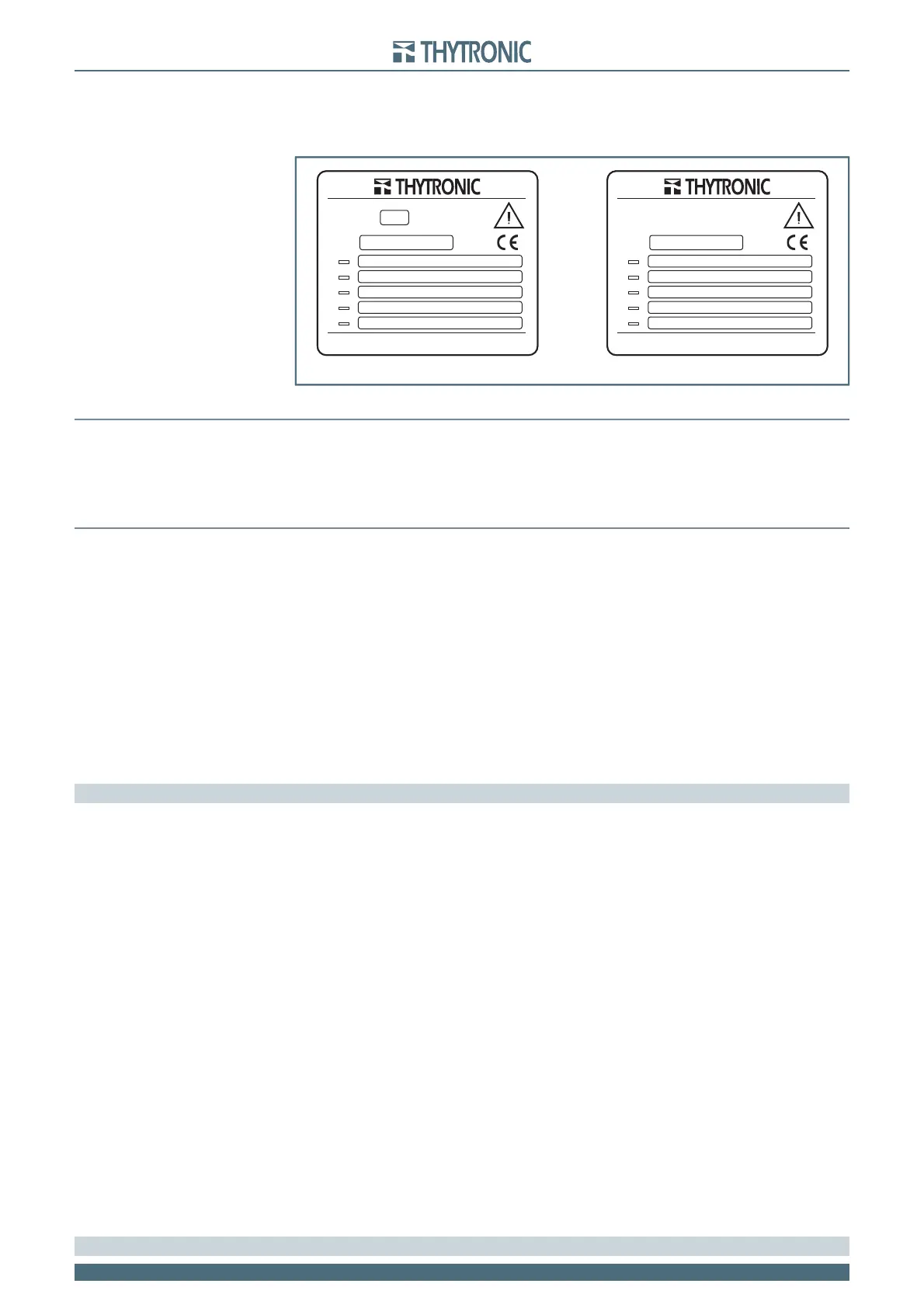
Each device is equipped with:
Identifi cation label installed on the front side with following informations: code number, phase and
residual nominal currents, auxiliary voltage range and CE mark:
Test label with following informations: data, serial number and test operator signature.
Environment
The NV10 device must be employed according to the environment conditions shown (see technical
data).
In case of different environment conditions, appropriate provisions must be provided (conditioning
system, humidity control, etc...).
If contaminants are present (dust, corrosive substances, etc...), filters must be provided.
Graphical conventions
The CEI/IEC and ANSI symbols is employed where possible:
e.g.: 27= ANSI code concerning the undervoltage element.
Following text formats are used:
The ThySetter
[1]
menu:
Undervoltage - 27
The parameter description (measures, thresholds, operate time,...) and related value:
U> element
Defi nite time
U>def
The display messages (MMI) are shown as:
NV10
Notes are highlighted with cursive letters inside colored bar
Note: Useful description note
Glossary/defi nitions
27 Undervoltage ANSI code
59 Overvoltage ANSI code
59N Residual voltage ANSI code
81O Overfrequency ANSI code
81U Underfrequency ANSI code
81R Frequency rate of change ANSI code
BF Breaker Failure
74VT VT monitoring
74TCS Trip Circuit Supervision
DFR Digital Fault Recorder (Oscillography)
SER Sequential Event Recorder
SFR Sequential Fault Recorder
ANSI American National Standard Institute
IEEE Institute of Electrical and Electronics Engineers
IEC International Electrotechnical Commission
CENELEC Comité Européen de Normalisation Electrotechnique
52 o CB (Circuit Breaker) Circuit Breaker
52a Auxiliary contact in the breaker that is in the same position as the
breaker. It can be assigned to a binary input to locate the CB posi-
tion (Breaker failure and/or CB diagnostic functions). (52a open = CB
open)
52b Auxiliary contact in the breaker that is in the opposite position as the
breaker (52b open = CB closed)
Note 1 The graphic interface and the operation of the ThySetter software are described in the relative chapters
•
•
NV10P#JA2MM00
U
AUX
110-230 Vac/dc
100V
100V
U
En
U
n
1
2
3
4
5
NV10P#0A2MM02
U
AUX
110-230 Vac/dc
20 kV
U
NP
1
2
3
4
5
Inductive VT versions Electronic sensor versions
NV10P#JA2MM00
U
AUX
110-230 Vac/dc
100V
100V
U
En
U
n
1
2
3
4
5
NV10P#0A2MM02
U
AUX
110-230 Vac/dc
20 kV
U
NP
1
2
3
4
5
Inductive VT versions Electronic sensor versions