63
NV10P - Manual - 01 - 2015
CHARACTERISTICS
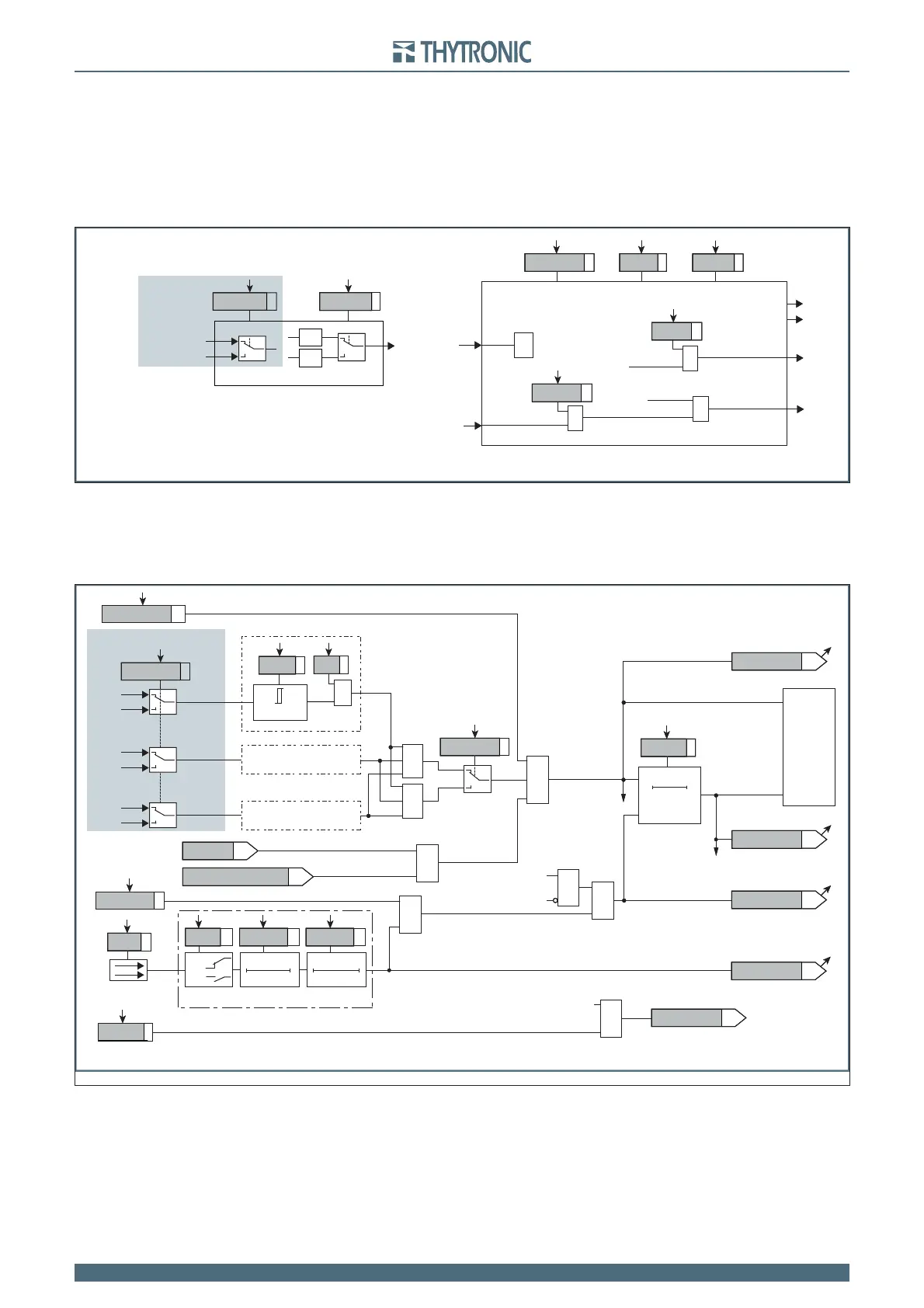
With inputs from sensors versions, the type of measurement of line-to-line voltages and phase volt-
ages may be select: the Utype59Uavg parameter in the Set \ Profi le A(or B) \ Average overvoltage-
59Uavg \ Common confi gurations menu may be set. The possible settings are Uph-ph (voltages) or
Uph-n (phase voltages).
The element can be disabled in the case of connection of the measuring inputs (TV or TV-I-NI) down-
stream of the Device Interface when the DI is open.
The threshold disabling is selected by setting ON the Uavg>disbyCB_OPEN parameter, inside the
Set \ Profi le A(or B) \ Average overvoltage-59Uavg \ Uavg> Element \ Setpoints menu.
Breaker failure (BF)
The average overvoltage element can produce the Breaker Failure output if the Uavg> BF param-
eter is set to ON.
The parameter is available inside the Set \ Profi le A(or B) \ Average overvoltage - 59Uavg \
Uavg> Element \ Setpoints menus.
Logical block (Block1)
If the Uavg>BLK1 enabling parameter is set to ON and a binary input is designed for logical block
(Block1), the protection is blocked off whenever the given input is active.
The trip timer is held in reset condition, so the operate time counting starts when the input block goes
down. The enabling parameters are available inside the Set \ Profi le A(or B) \ Average overvoltage
- 59Uavg \ Uavg> Element \ Setpoints menus, while the Block1 function must be assigned to the
selected binary input inside the Set \ Inputs \ Binary input IN1(x) menus (IN1 or INx matching).
All the parameters can be set separately for Profi le A and Profi le B.
all-F59Uavg.ai
U
Uavg> Element
Start Uavg>
Trip Uavg>
t
Uavg>
def
Uavg>
def
Uavg> Enable
Block1
BLK1Uavg>
&
Uavg>BLK1
Start Uavg>
&
Uavg>BF
Trip Uavg>
&
Uavg>BF
U
xxavg
¥
AND
U
12
,U
23
,U
31
U
U
L1
,U
L2
,U
L3
OR
Common configuration
Only with sensor versions
Utype59Uavg
Logic59Uavg
General logic diagram of the average overvoltage elements - 59Uavg
General logic diagram of the average overvoltage threshold - 59Uavg>
Trip Uavg>
BF Enable (ON≡Enable)
towards BF logic
&
Uavg> BF
RESET
t
Uavg>def
0T
TRIPPING MATRIX
(LED+RELAYS)
t
Uavg>def
Start Uavg>
Uavg>ST-K
Start Uavg>
Uavg>TR-K
Uavg>ST-L
Uavg>TR-L
Trip Uavg>
Trip Uavg>
Uavg>BF
BLK1Uavg>
&
&
&
Block1 input (ON≡Block)
Uavg>BLK1
Block1
Block1
Binary input INx
T0
Logic
INx
t
ON
INx
t
ON
INx
t
OFF
T0
n.o.
n.c.
INx
t
OFF
&
Logic59Uavg
≥1
&
Utype59Uavg
U
L1
U
12
U
L2
U
23
U
L3
U
31
&
State
U ≥
U
avg
>
def
U
avg
>
def
ON≡Enable Uavg> overvoltage element
Uavg> Enable
Only for sensor versions
≥1
(1≡DDI closed)
DDI state
(1≡upstream)
Uavg>
disbyCB_OPEN