14
All connections must be made before sealing the TileVision
®
into the back box.
TileVision
®
Connectors
To view television channels correctly, a signal must be received by
the TileVision
®
from one of the following sources:
an outdoor antenna
a cable television system
a satellite receiver.
Antenna Feed
Connect the antenna or input cable to the 75Ω coaxial connector
on the rear of the TileVision
®
.
Picture quality is determined by the signal level, it is
recommended that a qualified aerial technician is consulted.
Antenna input on
the TileVision
®
Cable Television
Network
or
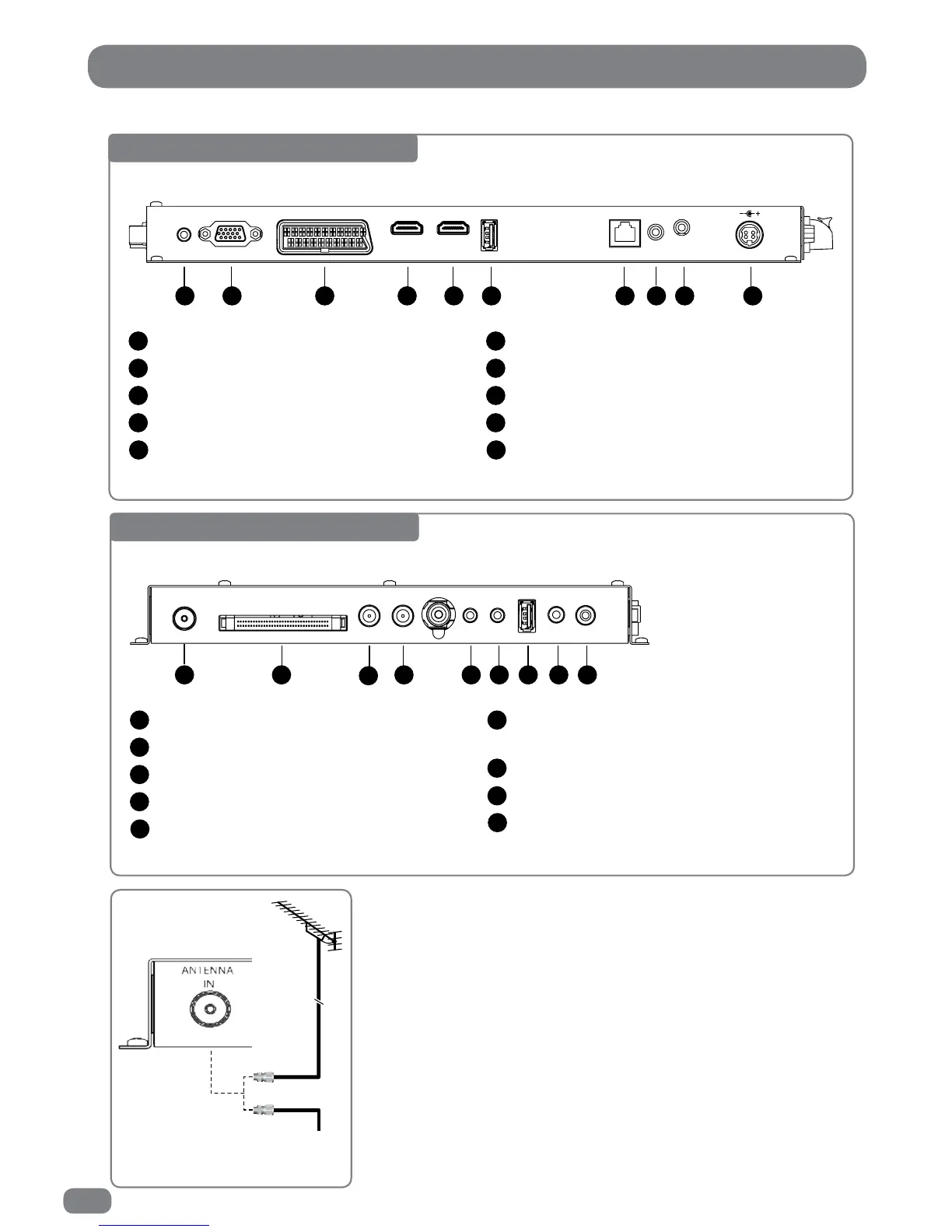
Base Connector Array
USB 1(USB Memory Stick / Flash Drive)
RJ12 – for Hotel TV System Integration
Infrared Link – In
Infrared Link – Out
DC 24V Power In
6
7
8
9
10
1 2 3 4 5 6 7 8 9 10
PC AUDIO
IN
VGA IN
SCART IN
HDMI 1 IN
HDMI 2 IN
USB 1 IN
RJ 12
IR Link
OUT
IN
24v DC
3.75 A
PC Audio In
VGA Input (D-SUB)
EURO-SCART
HDMI 1 (High Definition Multimedia Interface)
HDMI 2 (High Definition Multimedia Interface)
1
2
3
4
5
Side Connector Array
Composite Video Input (CVBS), Left & Right
Audio Input
USB 2 (USB Memory Stick / Flash Drive)
Audio Out (headphones)
SPDIF Out
6
7
8
9
1 2
3
4 5 6 7 8 9
ANTENNA
IN
CI PORT
LOOP OUT
SATELLITE
IN
COMPONENT
IN
AV &
L/R AUDIO IN
USB 2 IN
EARPHONE
OUT
SPDIF OUT
Antenna Input 75 Ω
CI Port for Conditional Access Module (CAM)
Satellite In
Satellite (Loop Out)
Component Video Input (Y, Pb (Cb), Pr (Cr)
1
2
3
4
5