TH2883 Series Operation Manual Chapter 9 Handler interface
9-4
when use.
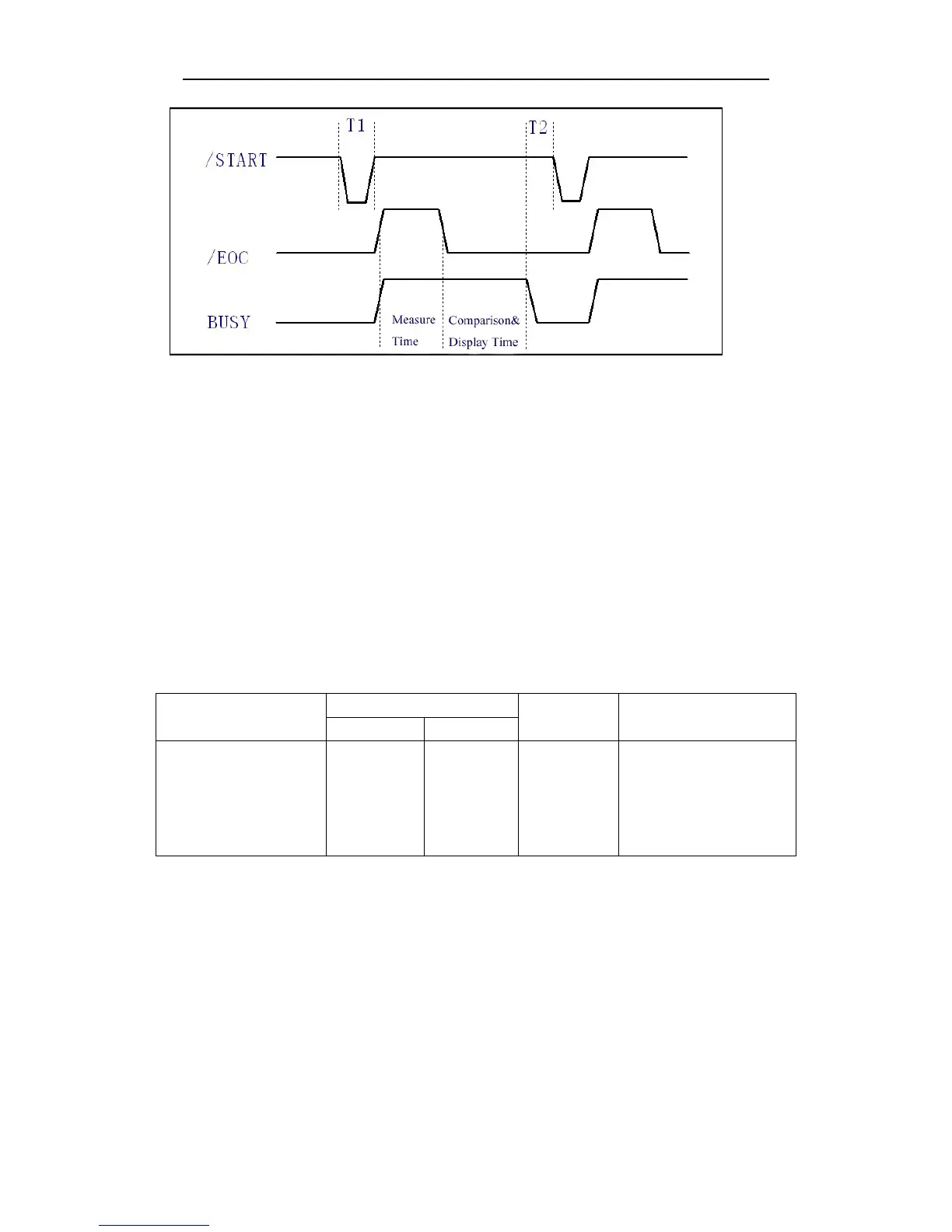
The timing diagram for handler interface is displayed in above figure, T1 is the trigger pulse width
and the minimum pulse width is 1 us. T2 is the delay time, after the foregoing measurement
completed to next trigger signal; its minimum pulse width is 0 us. /PASS and /FAIL signals are
asserted after the measurement completed, till next trigger. The request of the /STOP pulse signal is
the same as /START pulse signal.
9.2 Electrical characteristics
9.2.1 DC isolated output
Each DC output (pins 2 through 5) is the collector output of the built-in pull-up resistor and
isolated by an opto-coupler. The output voltage of each line is set by a pull-up resistor on the
handler interface board. The pull-up resistors can be connected to the internally supplied voltage
(+5V), or to an externally applied voltage (EXV: +5V to +24V) by setting jumpers. Table 9-1
shows the electrical characteristics of the DC isolated outputs.
Table 9-1 DC isolated output electrical characteristics
Output signal
Voltage output rating
Maximum
current
Circuit common
Low High
/EOC
BUSY
/PASS
/FAIL
≤0.5V
+5V~
+24V
6mA
Internal pull-up voltage:
TH2883 series circuit
common GND
External voltage (EXV):
EXGND