TH2883 Series Operation Manual Chapter 9 Handler interface
9-5
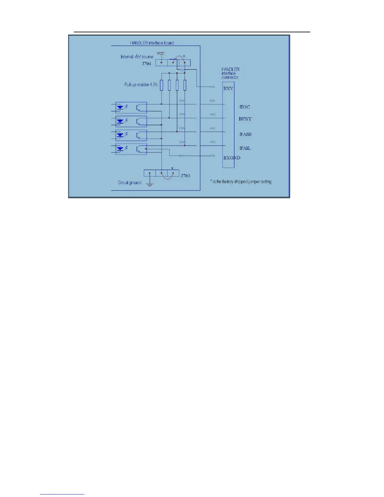
Figure 9-1 Simplified diagram of the output signals
A simplified diagram of the output signals is shown in Figure 9-1. * is the default jumper setting
when shipped from factory. That is to say, the default jumper setting is to use external voltage
source.
Refer to the next section Jumper Setup.
9.2.2 Isolated input
The /START signal (pin 7) and the /STOP signal (pin 8) are connected to the cathode of the LED in
an opto-coupler. TH2883 series is triggered on the rising edge of the /START pulse and stopped on
the rising edge of the /STOP pulse. The anode of the LED can be connected to the internal +5V, or
an external voltage source EXV (the same external voltage source used for output signal).