EasyManua.ls Logo

Toptech MultiLoad II EXL - Additive Wiring: Inputs

Toptech MultiLoad II EXL
83 pages
To Next Page IconTo Next Page
To Previous Page IconTo Previous Page
Loading...
CHAPTER 5 CONNECTING FIELD DEVICES TO THE I/O BOARD
42 MultiLoad II/ RCU II Explosion Proof Lite (EXL) Installation Guide - Part # 6070
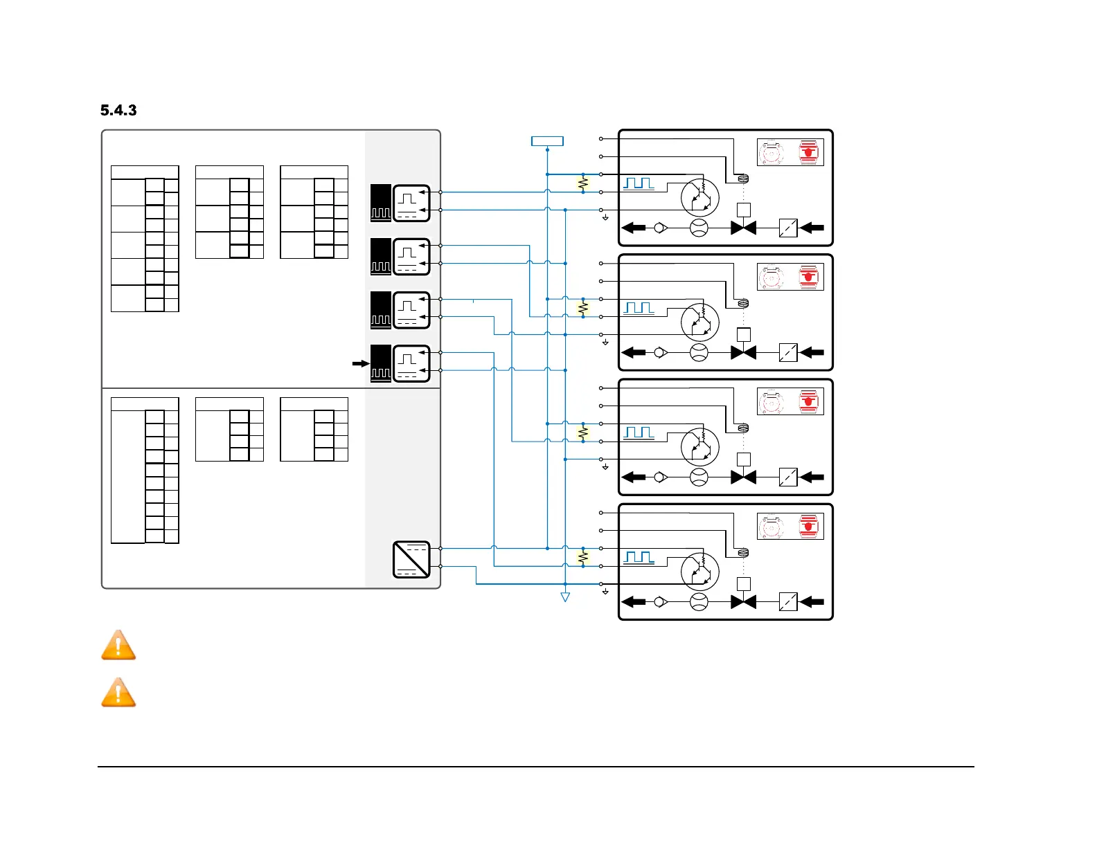
MultiLoad II Additive Wiring: Inputs
I/O DIGITAL/
ANALOG
I/O 2 METER
METER 0 METER 1
PORT 4.+
PORT 4.-
PORT 5.+
PORT 5.-
+
-
1
PORT 4
+
-
2
+
-
3
+
-
4
+
L
N
S
#1
+
L
N
S
#2
+
L
N
S
#3
+
L
N
S
#4
PORT 5
PORT 6/
PORT 7
+
-
5V
12V
+
1
-
2
+
3
-
4
+
5
-
6
+
7
-
8
+
9
-
10
IO_DA TB2B
PORT 4
PORT 5
PORT 6
PORT 7
PORT 9
+
1
-
2
+
3
-
4
+
5
-
6
IO_2M TB7
PORT 4
PORT 5
PORT 7
+
1
-
2
+
3
-
4
+
5
-
6
IO_2M TB8
PORT 4
PORT 5
PORT 7
PORT 7
IO_DA ONLY!
PORT 7.+
PORT 7.-
PORT 6.+/
PORT 6.-/
PORT 7.+
PORT 7.-
+ 1
+ 2
- 3
-
4
IO_2M TB6
12Vdc
+ 1
+ 2
- 3
-
4
IO_2M TB6
12Vdc
+
1
+
2
+
3
+
4
+
5
-
6
-
7
-
8
-
9
-
10
12Vdc
IO_DA TB2A
~1 kΩ,
1/4W
~1 kΩ,
1/4W
~1 kΩ,
1/4W
~1 kΩ,
1/4W
12Vdc
*
*
*
*
*Note: Most additive injection meters only provide an Open-Collector (pull down) type output. Typically a 1,000 Ohm, ¼ watt pull-up resistor needs
to be added in the pulser junction box to pull this output to 12V+ when the output is off.
Note (I/O 2 METER Only): TB7 pins 3 and 4 can be configured as Port 5 or Port 6. It is only 1 port, but because of the logic in the firmware, it may
be necessary to address it as Port 5 or Port 6 in the configuration.

Table of Contents

Related product manuals