EasyManua.ls Logo

Toptech MultiLoad II EXL User Manual

Toptech MultiLoad II EXL
83 pages
To Next Page IconTo Next Page
To Previous Page IconTo Previous Page
Page #24 background image
CHAPTER 3 INSTALLING THE MULTILOAD II/RCUII EXL
24 MultiLoad II/ RCU II Explosion Proof Lite (EXL) Installation Guide - Part # 6070
DC Powered Models
The MultiLoad II/ and RCU II is optionally available with a 24 Vdc power supply. The power source
used to supply the MutliLoad II/RCUII must be rated 9 30 Vdc SELV, Limited Energy (Class 2). The
rated supply input current is 600mA. The supply should be protected by a 1.5 Amp fuse.
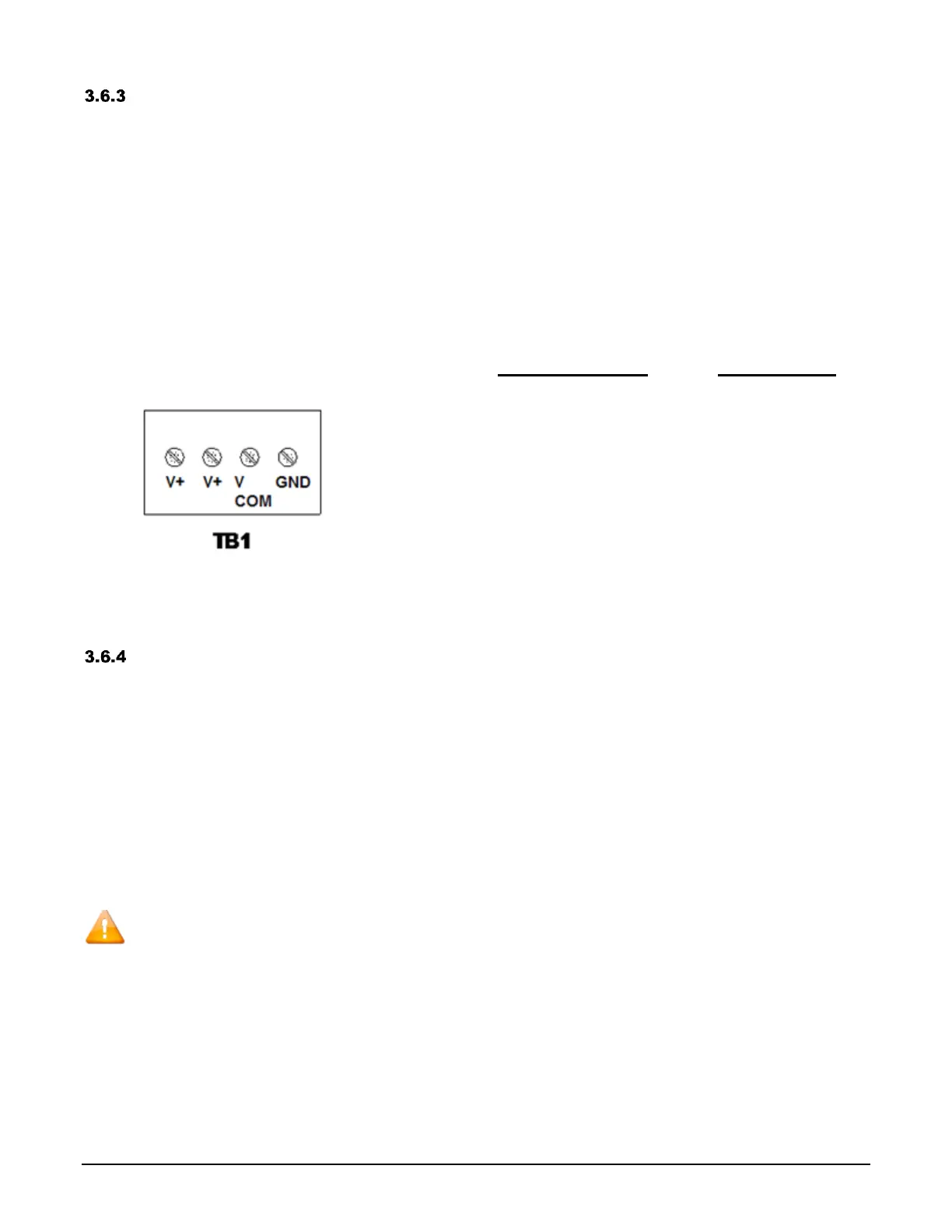
The 4-position terminal block is located in the right-hand corner of the power supply/communication
board. The left-most terminal position is a spare and will not be used.
Figure 3.4 DC Power Connections
Wiring guidelines for using 24 Vdc power
supply:
Wire gauge (AWG)
Distance (feet)
24
50
22
100
20
150
18
250
16
400
Equipment Grounding
A safety ground should be attached to terminal block TB1 (on both ac and dc input power models) to
maintain electrical safety in the event of a fault condition. Follow the terminal block wiring instructions
in section 3.6. Keep the required tightening torque in mind (section 3.5).
The external ground connection is not provided for the attachment of the protective conductor (the
safety ground). Rather, it is provided only as a supplemental bonding connection where local
authorities permit or require such a connection: for example, as a means of equipotentiality. The wire
connection is on the bottom right exterior surface. The following wire sizes may be used: 10 AWG
(5.26 mm
2
) or 11 AWG (4.17 mm
2
).
Do not connect the power supply dc common to earth ground.

Table of Contents

Question and Answer IconNeed help?

Do you have a question about the Toptech MultiLoad II EXL and is the answer not in the manual?

Toptech MultiLoad II EXL Specifications

General IconGeneral
BrandToptech
ModelMultiLoad II EXL
CategoryController
LanguageEnglish

Summary

Chapter 1 General Information & Warnings

Safety Warnings

Critical safety precautions for North American and ATEX/IECEX hazardous locations.

Electrostatic Discharge (ESD) Protection

Guidelines for handling components to prevent damage from electrostatic discharge.

Chapter 2 Operating Conditions and Components

Operating Characteristics

Key operational specifications and electrical ratings for internal I/O options.

Chapter 3 Installing the MultiLoad II/RCUII EXL

Mounting the DIV-2 Enclosure

Guidelines and suggestions for mounting the EXL enclosure on various surfaces.

Electrical Supply Connections

Instructions for connecting AC and DC power supplies, including cable gland details.

Chapter 4 Data Communications Interface

Communications Protocols and Wire Specs

Details on RS-422/485 and RS-232 protocols, including wire requirements.

Communication Connection Wiring

Wiring connections for specific communication protocols like FCM.

Host/TMS Communications

Methods for connecting host/TMS computer systems via various communication ports.

Host Ticket Printer/Data Logger Connections

Connection options for ticket printers and data loggers via RS232 or Ethernet.

Chapter 5 Connecting Field Devices to the I/O Board

Available I/O Points per Board

Quantities and electrical ratings of I/O points for Digital/Analog and 2 Meter I/O boards.

Terminal Arrangements per Board

Terminal block assignments for the Digital/Analog I/O Board (IO_DA).

How to Connect and Wire Field Devices

Examples of wiring common field devices to the I/O boards.

Flow Meter and Control Valve Wiring

Wiring diagrams for connecting flow meters and control valves.

Additive Wiring: Outputs

Diagrams for connecting additive injection outputs to the I/O board.

Chapter 6 Configurations

Switch Access Control

Details on switches that limit access to program mode and W&M parameters.

Verifying Communications

Steps to verify communication between MultiLoad II/RCU II and the I/O board.

Chapter 7 Service and Repair

CPU Subassembly Removal and Replacement

Procedure for removing and replacing the CPU chassis, boards, and optional I/O board.

Display Subassembly Removal and Replacement

Procedure for removing and replacing the display module and its associated cables.

Keypad Removal and Replacement

Procedure for removing and installing the unit keypad and bezel.

Keypad Barrier Removal and Replacement

Procedures for removing and replacing keypad barrier versions 1.1 and 2.0.

Card Reader Removal and Replacement

Procedure for removing and installing the EXL Prox Card Reader.

W&M Switch Assembly Removal and Replacement

Procedure for replacing the W&M switch assembly.

Chapter 8 Hardware Revision History & Compatibility

Chapter 9 Revision History

Related product manuals