CHAPTER 6– CONFIGURATIONS
59 MultiLoad II/ RCU II Explosion Proof Lite (EXL) Installation Guide - Part # 6070
Internal Switch Access Control
Two DIP switches on the CPU board also provide the closure of the program mode / W&M switch
contacts. When the MultiLoad II/ RCU II does not have the external Program Mode / W&M switch
installed, it is necessary to use these DIP switches on the CPU board to enable program mode and
W&M access.
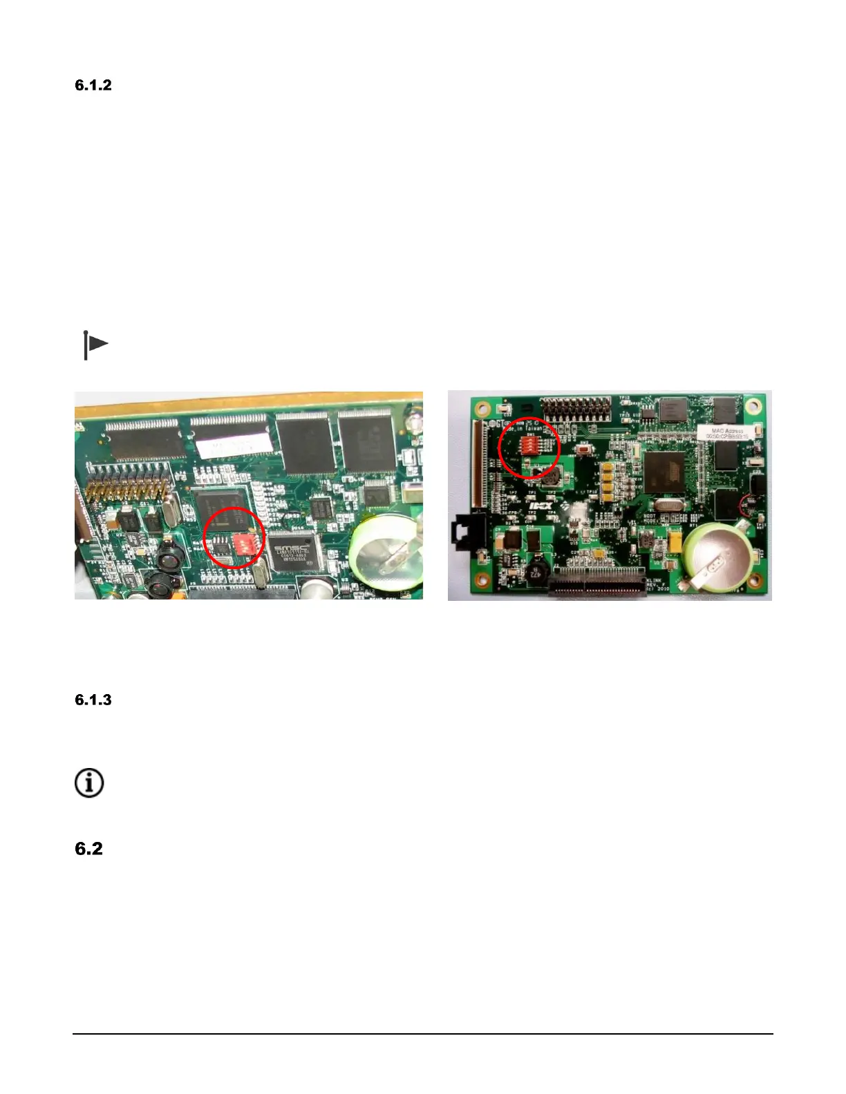
The switches are numbered 1 through 4, with 1 being closest to the front of the enclosure (top of the
picture), and 4 being towards the back of the enclosure (bottom of the picture).
When the switch is in the ON position, the switch is in the active state, allowing access. A switch is ON
when it moves right, and OFF when moved to the left.
Switch #3 is the program mode switch. Switch #4 is the W&M access switch. In the example in Figure
6.4 below, the program mode switch is currently active, while the W&M switch is not active. Figure 6.5
shows the location of the DIP switch on revision 2.x CPU boards.
A switch input is active when either the DIP switch OR the external switch is active (ON).
Figure 6.4 CPU DIP Switches for Program
and W&M Access (rev 1.0)
Figure 6.5 CPU DIP Switches for Program
and W&M Access (rev 2.x)
Field Switch Access Control
The MultiLoad II also has the ability to accept field inputs for the program mode and W&M access
switches. Review the “MultiLoad II User Guide” for more information.
RCU II INPUTS RECEIVED FROM EXTERNAL FIELD DEVICES CANNOT BE CONFIGURED TO CONTROL
PROGRAM MODE ACCESS. WEIGHTS AND MEASURES FUNCTIONALITY IS UNDEFINED FOR RCU II.
MultiLoad II/ RCU II DIV-2 Keypad
The MultiLoad II/ RCU II EXL keypad has 22 keys, including alpha/numeric and function keys, used to:
- Select menu items and fields
- Enter data in fields
- Initiate actions
- Return to previous screens