Feedback Controlyzer DigiLock 110
Page 8
Status: 5.12.17
3 Operator Controls and Connections
3.1 Front Panel
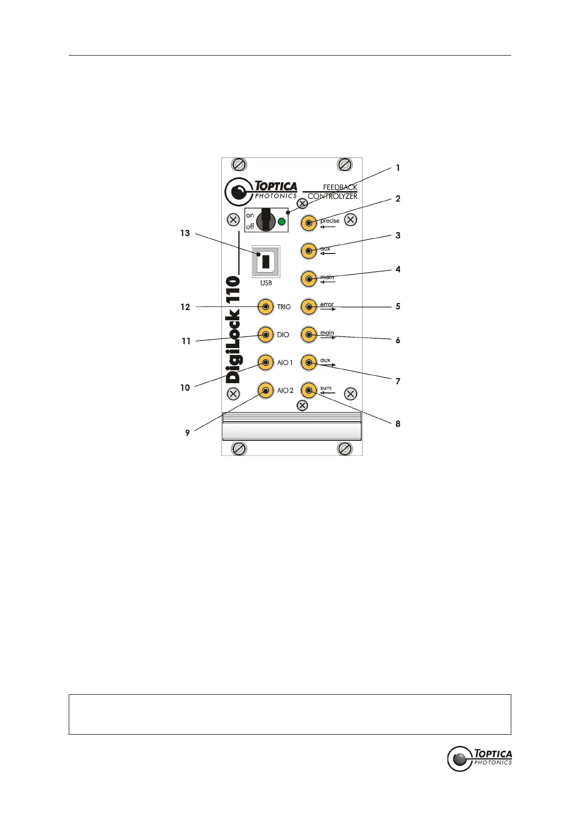
Figure 4 Front panel of the DigiLock 110
1 ON/OFF switch and indicator
LED
6 Main
high-speed analog output
11 DIO
General purpose digital input/
output
2 Precise
analog input
7 Aux
high-speed analog output
12 Trigger output
3 Aux
high-speed analog input
8 Sum input 13 USB connector
4 Main
high-speed analog input
9 AIO 2
General purpose analog
input/output 2
5 Error output 10 AIO 1
General purpose analog
input/output 1
CAUTION ! All high-speed inputs are 50 Ohm terminated by default and all high-speed outputs includ-
ing Trigger output (12) are able to drive 50 Ohm loads. If needed, the inputs can be con-
figured to high impedance by changing internal jumpers (for details see section 9.1)
 Loading...