Feedback Controlyzer DigiLock 110
Page 10
Status: 5.12.17
3.3 Backplane Connections
The DigiLock 110 module is capable of accessing several analog signals on the backplane of the
Sys DC 110 rack. On the one hand analog signals can be set in order to remote control other modules
(see Table below). On the other hand actual parameters of modules can be read (DCC 110 I
act
,
DTC 110 I
act
). Currently, only the actual values of the channel 1 modules (Figure 5: slots 2 + 3) can be
read by the DigiLock 110 (see Sys DC 110 manual for details).
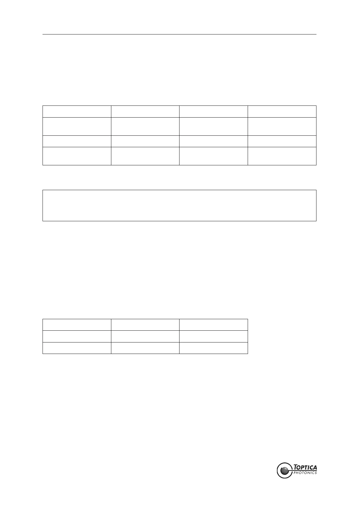
Table 1 Backplane outputs of the DigiLock 110 and their assignment
Make sure that no module other than the SC 110 uses the #DA 2 analog backplane line. By default the
DigiLock 110 communicates via #DA 2 with the SC 110. If you do not need this functionality, you can dis-
connect #DA 2 from the backplane by removing the appropriate jumper (see section 11.2). In addition
to the SC 110 output there is are two more backplane outputs: DCC 110 I
set
(#DA 1) and DTC 110 T
set
(#DA3), which can be activated by setting the corresponding internal jumper (see section 11.2). Gener-
ally, theses outputs can be used to adjust for stable single mode operation using the computer interface.
Adjusting the laser diode temperature via DTC 110 T
set
(#DA3) is of particular interest for scanning the
wavelength of DFB laser diodes.
The DigiLock 110 can read the DCC 110 I
act
and DTC 110 T
act
parameters via the backplane (see sec-
tion 11.4 for details). This readout only works when the DigiLock 110 as well as the modules to be read out
are installed on channel 1 of the rack (slot 2, 3 and 6). It is recommended to install the DigiLock 110 in slot
6 (see Figure 5). For further information on the arrangement of the modules please see the Sys DC 110
manual.
Table 2 Backplane inputs accessible by the DigiLock 110 and their assignment
Backplane Line Adressed Module Parameter Comment
#DA 1 DCC 110 I
set
not jumpered
by default
#DA 2 SC 110 Offset jumpered by default
#DA 3 DTC 110 T
set
not jumpered
by default
NOTE ! The assignment of the #DA-lines to the respective parameter is fixed inside the
DigiLock 110 module. Be sure that the jumpers of the corresponding modules are set
according to the table above. For detailed information please see the appropriate sec-
tions in the Sys DC 110 manual.
Backplane Line Adressed Module Parameter
I
act
Channel 1 DCC 110 I
act
T
act
Channel 1 DTC 110 T
act
 Loading...