10. Application Examples
Page 59
Status: 5.12.17
10.2.2 Top of Fringe Locking (Lock-In)
To lock the laser to a maximum of the Doppler-free absorption signal, a zero crossing slope is generated
using frequency modulation. The Lock-In module uses a modulation frequency smaller than the charac-
teristic resonance width to obtain the derivative of the absorption signal by demodulation.
For the setup follow the initial steps 1. to 18. described above, but choose <LI out> as input to the
AutoLock module.
21. To view the error signal switch to AutoLock display. Set the scan frequency of the Scan module to
10 Hz, the output to <SC 110 out> and switch on the scan.
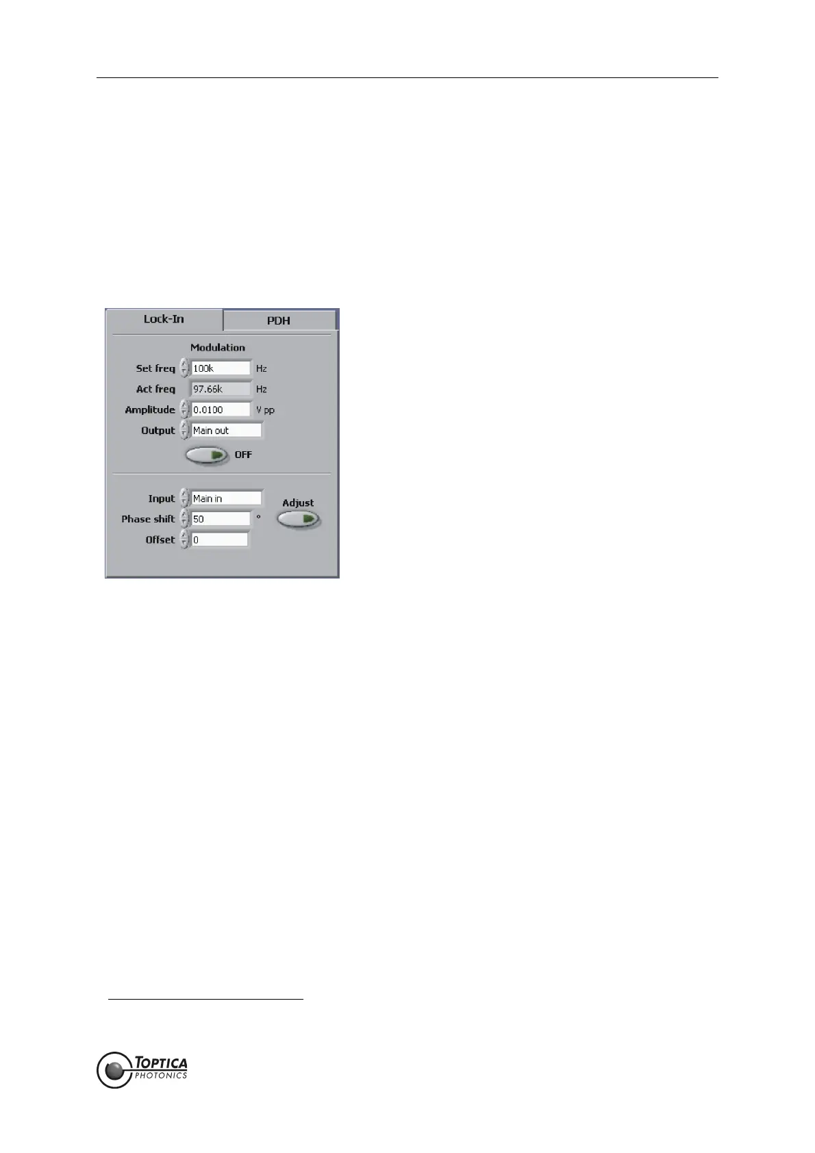
Figure 48 Lock-In module with typical parameters
22. Configure the parameters for the Lock-In module (see Figure 48). The modulation set frequency
(Set freq) must be chosen depending on the spectral resonance. A reasonable choice is about 1/
10 of the characteristic linewidth. In this example a frequency of about 100 kHz is used. Due to the
specific architecture of the DigiLock 110 only discrete frequencies are possible. Type in the desired
one and the system will automatically determine the nearest one available (Act freq).
23. Turn on the modulation by pressing the ON/OFF button. The second trace should now display the
error signal derived from the frequency modulation. The modulation amplitude is a trade-off
between the desired lock-in signal strength and the allowed frequency modulation of the laser.
The larger the amplitude, the larger the lock-in signal but note that at the same time the side-
bands on the laser increase
13
.
Figure 49 shows the resulting Scope display (with optimized phase).
13. This tradeoff can be eliminated by using an additional electro-optical modulator (EOM) in the locking beam path after
splitting from the main beam.
 Loading...