8. DigiLock User Interface (DUI)
Page 31
Status: 5.12.17
8.2.4 System
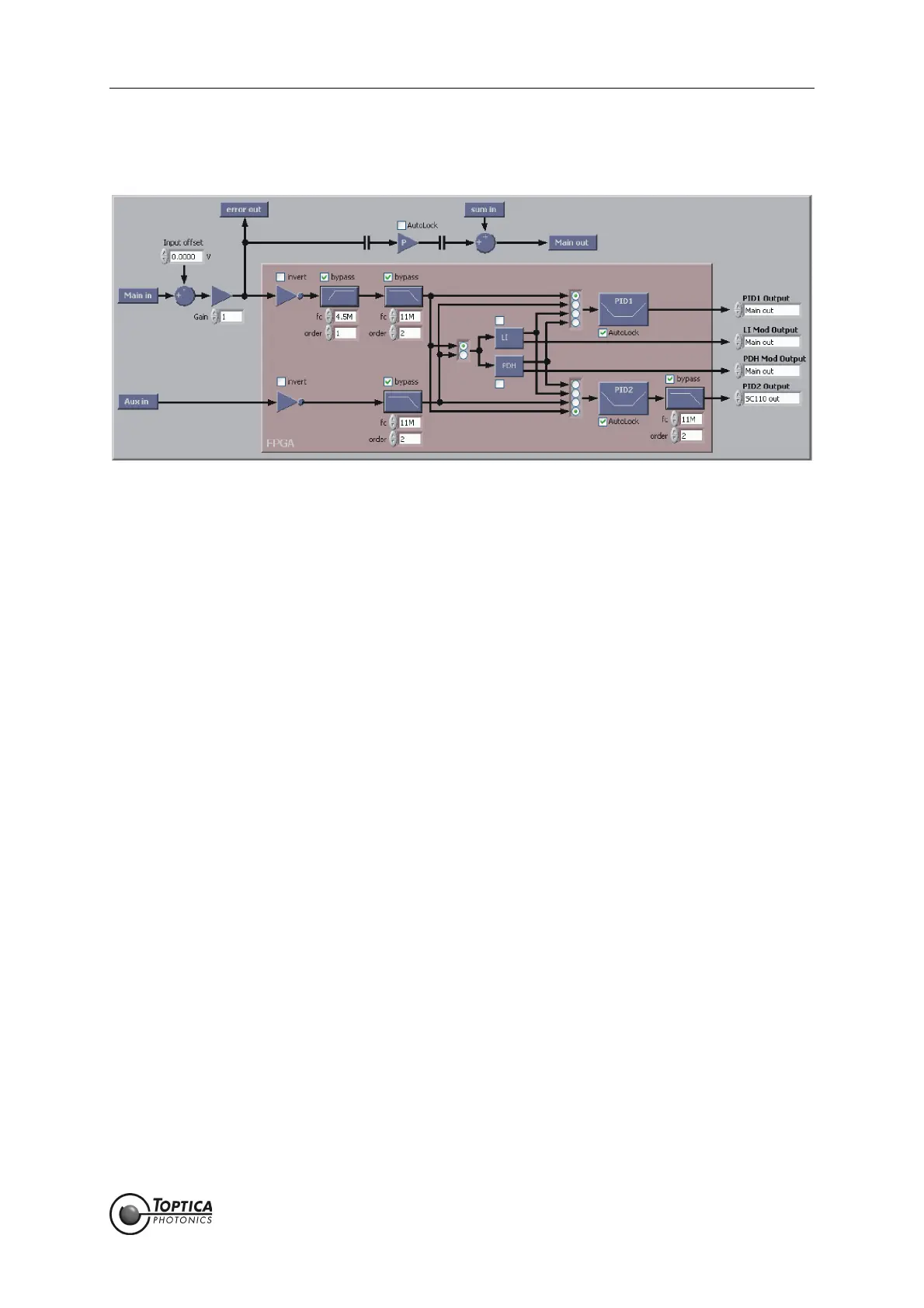
Figure 19 System overview of the current configuration of the signal path. Particularly allows to config-
ure the main input offset and gain as well as filters
Schematic of the high-speed signal path inside the DigiLock 110 module indicating the current configu-
ration. Some parameters can only be set on this screen (<Main in> input offset, <Main in> gain, invert sig-
nal, all kinds of filters). All parameters set here are automatically updated throughout the whole system.
The filters (three low-pass and one high-pass) are either configured via the corresponding input fields
(fc: cut-off frequency, order of the filter). Alternatively, pressing the filter symbol opens a screen which
shows the simulation of the transfer function of the filter with the specified parameters. By modifying the
parameters (fc, order) you can change this transfer function. Pressing OK confirms the parameters and
transfers them to the setup.
Note that the filters introduce additional phase lags and delays corresponding to the processing time.
The processing time for an active low-pass filter is (2+order) x 10 ns, for an active high-pass filter
(1+order) x 10 ns.
 Loading...