8. DigiLock User Interface (DUI)
Page 39
Status: 5.12.17
8.3.2 AutoLock
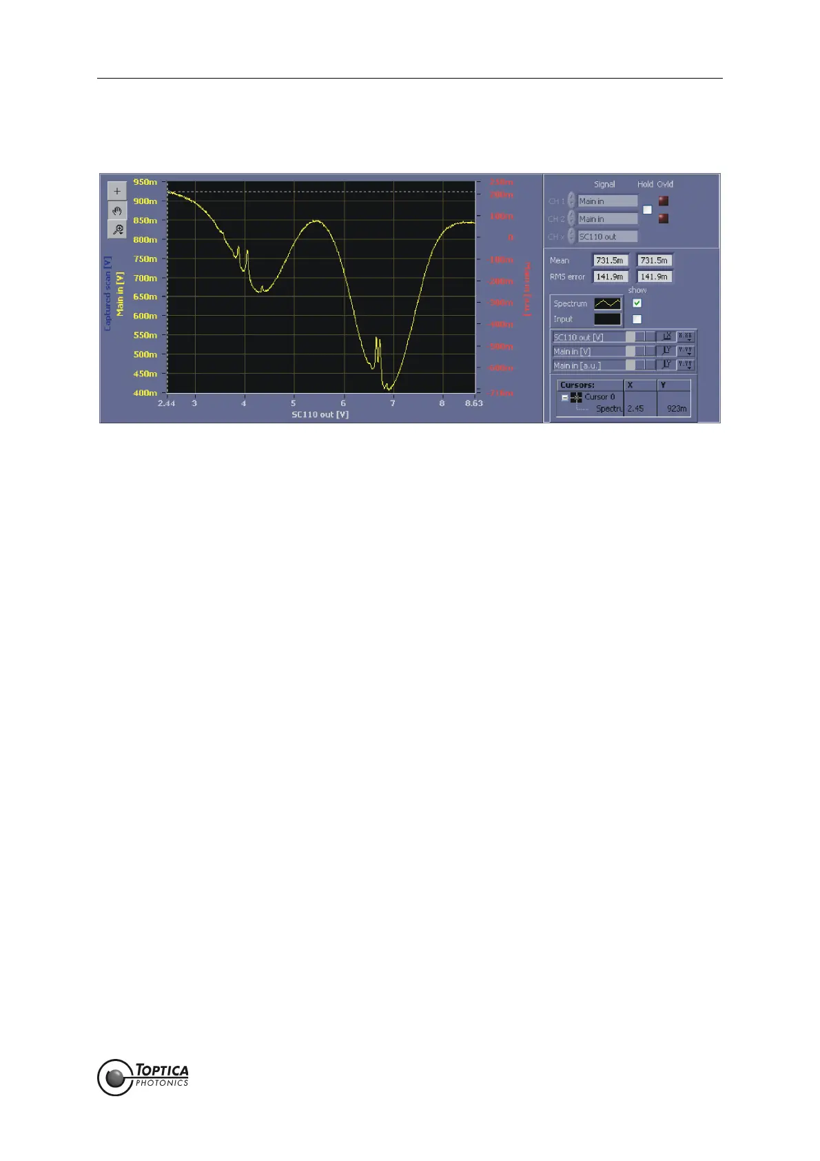
Figure 29 AutoLock display
This display is used in conjunction with the AutoLock module in the upper part of the screen. In this display
the user can handle two major tasks:
• Search the desired lock point via panning and zooming the displayed signal.
• Initiate the locking procedure with the help of the context menu.
CH 1: Can not be modified.
Spectrum signal chosen in the AutoLock tab (see Figure 11).
CH 2: Can not be modified.
Input signal chosen in the AutoLock tab (see Figure 11).
CH x: Signal displayed on the x-axis. Given by the output of the Scan module.
Hold: Freezes the trace.
Ovld: Indicates whether the selected channel was at its limits during the last
acquisition.
Mean: Mean value calculated from the trace for channel 1 and channel 2,
respectively.
RMS-error: RMS value calculated from the difference between the displayed trace
and its mean value.
The following shortcuts (AutoLock display only) allow a more convenient operation:
CTRL+<arrow left>: increases the offset of the x-channel by scan range*0.1
CTRL+<arrow right>: decreases the offset of the x-channel by scan range*0.1
CTRL+<arrow down>: increases the scan range of the x-channel to scan range*1.2
CTRL+<arrow up>: decreases the scan range of the x-channel to scan range/1.2
f allows stepping through the tool selection (cursor, pan, zoom)
 Loading...