Feedback Controlyzer DigiLock 110
Page 46
Status: 5.12.17
9.5 Relock Feature
The basis of the relock feature of the DigiLock 110 is the out of lock detection. It is based on a window
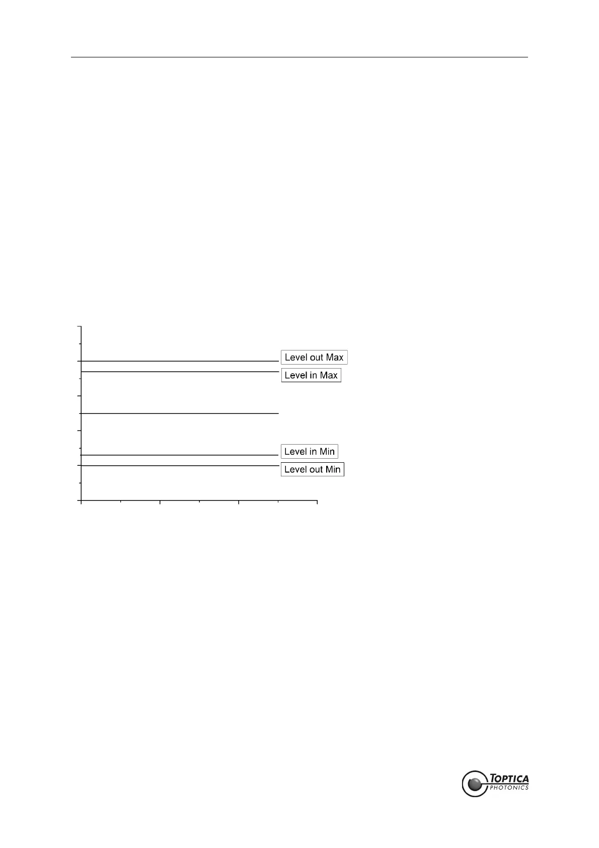
comparator which is defined by four parameters (see Figure 34):
•Level out Max
•Level out Min
•Level in Max
•Level in Min
Once the signal has left the "outer" window defined by <Level out Max> and >Level out Min>, the corre-
sponding PID controller is in hold state, i.e. its output is frozen. In order for the PID controller to reactivate,
the input signal must be within the "inner" window defined by <Level in Max> and <Level in Min>. With this
setup of four levels, a hysteresis behavior for the relock feature is implemented which is necessary to
allow for noisy input signals. It is recommended to choose the hysteresis (<Level out Max> - <Level in
Max> or <Level out Min> - <Level in Min>) larger than the input signal peak-to-peak noise.
The time between the detection of the unlocked state and the activation of the relock scan can be
set by the delay in the PID Window tab of the Settings function (see section 8.2.1.4). The output channel,
frequency and amplitude of the relock scan are defined in the AutoLock|Relock tab or the correspond-
ing PID controller.
Figure 34 Relock window.
The relock window is defined by the min and max values. When the signal leaves this window
the out of lock state is detected and the output of the controller is frozen. Once the signal
has reentered the inner 80 % window the system is considered to be locked again. The time
between detection of the out of lock state and the activation of the relock scan is defined
by the delay set in the AutoLock|Window tab.
Before starting the relock scan, the controllers can optionally be reset to zero using a finite slope defined
by the reset rates (see section 8.2.1.3 and 8.2.1.4 for details).
 Loading...