Feedback Controlyzer DigiLock 110
Page 22
Status: 5.12.17
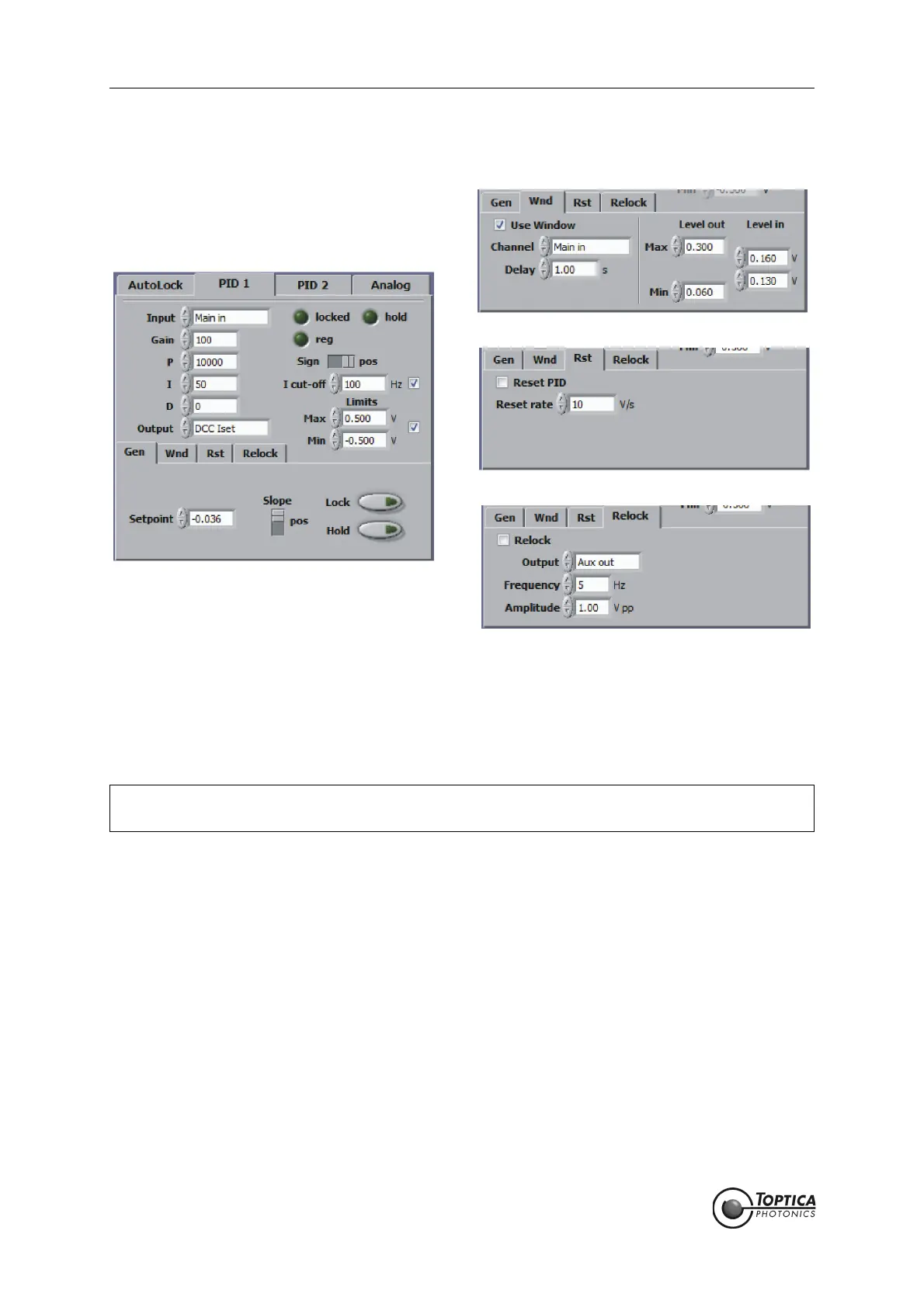
8.2.1.4 PID 1
Figure 12 PID 1 controller
The PID 1 is a standard PID controller with the special feature that the user can set a cut-off frequency
(I cut-off) below which the integral part is limited (as illustrated by the transfer function, section 8.2.2). This
limitation of the integral part is important in case PID 1 is used together with PID 2 in one control system. It
prevents the controllers from accumulating offsets in opposite directions.
Input: Input source for the controller (Main in, Aux in, LI out or PDH out). Cannot
be changed when this controller is active for AutoLock.
Locked LED: This indicator is on when the controller is on and - if activated - the
respective input channel value is within the comparator window.
Hold LED: This indicator is on when the controller is on hold.
Reg LED: This indicator is on when the controller is regulating.
Sign: Defines the polarity of the PID output with respect to the Scan module
output. In the typical setup the PID 2 output is directed to <SC 110 out>,
the PID 1 output to the current modulation input of the laser head and
the <SC110 out> used for scanning. In this case the PID 2 sign is positive.
The sign of PID 1 is defined by the polarity of the current controller
DCC 110. It is positive (negative) if the polarity of the DCC 110 is nega-
tive (positive) respectively. For details see section 9.4.
Gain: Overall gain.
NOTE ! When the controller is not selected for AutoLock, it can be used as an independent con-
troller (Manual Mode).
 Loading...