Feedback Controlyzer DigiLock 110
Page 48
Status: 5.12.17
10 Application Examples
There are numerous different schemes to stabilize lasers, for example to atomic or molecular resonances
and cavities. The DigiLock 110 is designed to cover a large range of locking scenarios. This section
describes step-by-step how to implement some of the most common ones with the DigiLock 110.
10.1 General System Setup
The general setup for the stabilization is shown in Figure 35. All locking schemes are based on a spectro-
scopic signal provided by the experimental setup which serves as a reference. The DigiLock 110 is capa-
ble of supplying the scan to find the resonance and lock point, derive the error signal and it provides the
controllers for the feedback loop. It can optionally generate an error signal by means of a frequency
modulation technique. Furthermore the graphical user interface supports both a user-friendly AutoLock
mode as well as intuitive access to all locking parameters. The integrated frequency analysis (Spectrum
display) allows to optimize the regulators in advanced applications.
This section introduces the common setup for the different locking scenarios described in the following
sections.
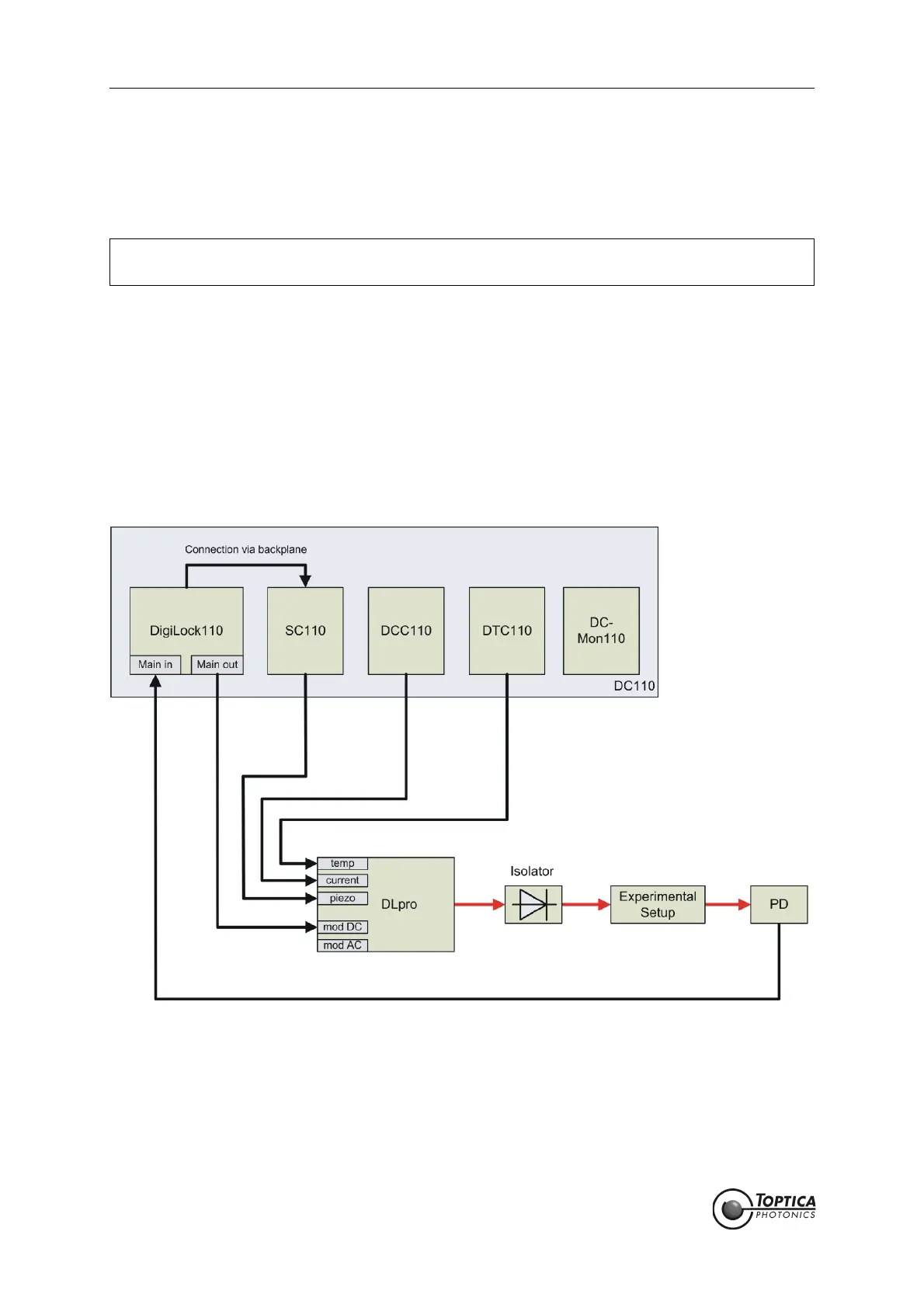
Figure 35 Typical setup for laser locking
The signal from the photo detector (PD) is fed into the <Main in> input of the DigiLock 110.
The two PID controllers act via the backplane and SC 110 on the grating piezo and via the
<Main out> on the laser diode current (mod DC).
NOTE ! This chapter assumes that the user has some basic knowledge of the laser system and the
electronics involved. For further information see the Sys DC 110 manual.
 Loading...