3. Operator Controls and Connections
Page 9
Status: 5.12.17
3.2 Description of Front Panel Operator Controls and Connectors
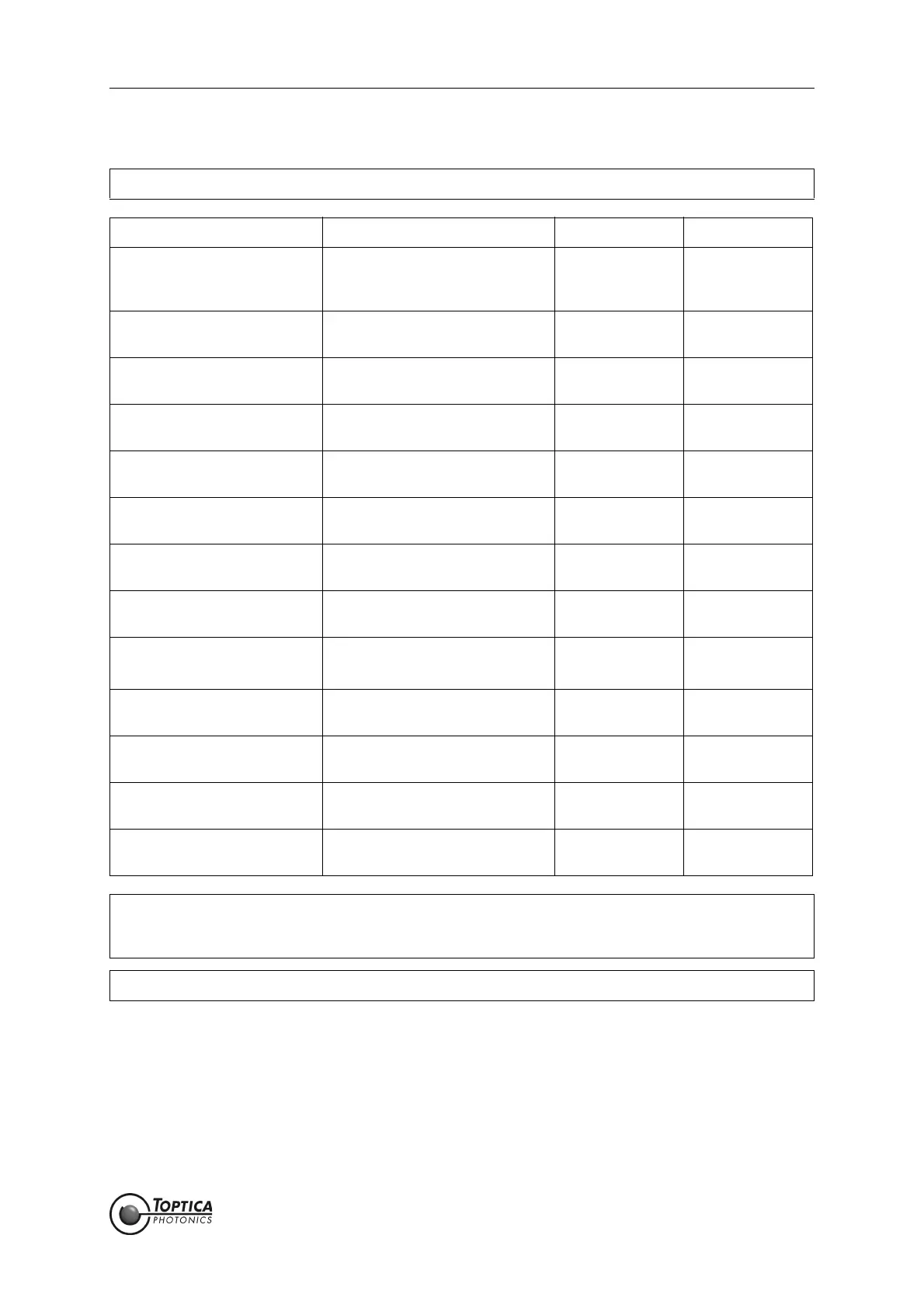
NOTE ! The values in the default configuration are set in bold letters.
Range [V] Impedance [Ω]
1 ON/OFF Switch
•Switch and LED
ON/OFF Switch for the main
power supply of the
DigiLock 110 module.
2 Precise input
• SMB-connector
Precision analog input ± 2 V 10k
3Aux in
• SMB-connector
High-speed analog input ± 2V 50
4Main in
• SMB-connector
Versatile high-speed analog
input
± 2V 50
5 Error output
• SMB-connector
Output of the error signal: (Main
in - Input offset) x Gain/2
± 1.7 V 50
6Main out
• SMB-connector
Versatile high-speed analog
output
± 1V 50
7Aux out
• SMB-connector
High-speed analog output ± 1V 50
8Sum input
• SMB-connector
Signal input is added to Main
out
± 1V 50
9AIO2
• SMB-connector
General purpose analog input/
output
Input: ± 12.5 V
Output: ± 6.5 V
Input: 47k
Output: high
10 AIO 1
• SMB-connector
General purpose analog input/
output
Input: ± 12.5 V
Output: ± 6.5 V
Input: 47k
Output: high
11 DIO
• SMB-connector
General purpose digital input/
output
0 V; 2.6 V TTL Input: 47k
Output:50
12 Trigger output
• SMB-connector
Trigger output 0 V; 2.6 V TTL 50
13 USB connector Connector for Computer Con-
trol
CAUTION ! The ON/OFF switch (1) should only be used when the laser is switched off.
Always first switch on the DigiLock 110 module, then start the DigiLock 110 software and
after that switch on the laser and vice versa.
NOTE ! For detailed connector specifications please see section 11.4.
 Loading...