8. DigiLock User Interface (DUI)
Page 19
Status: 5.12.17
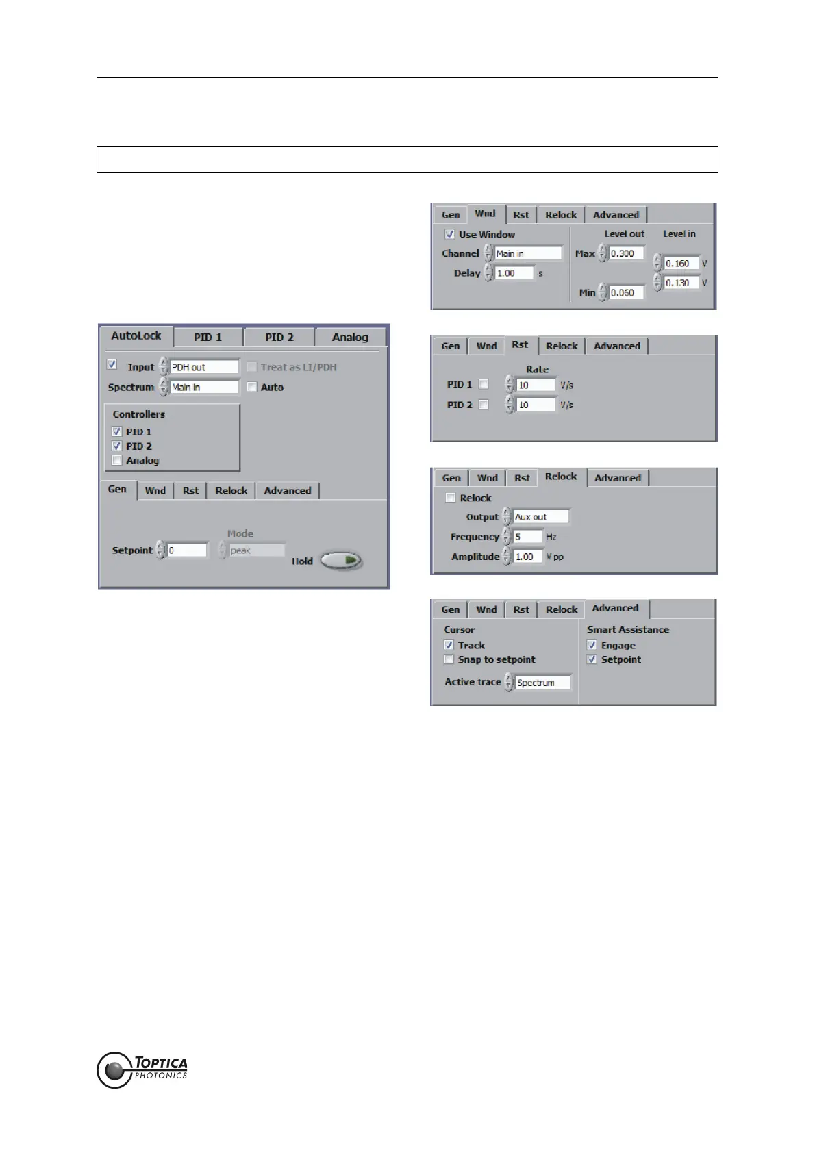
8.2.1.3 AutoLock
Figure 11 The AutoLock module combines several controllers to one with advanced locking features.
Advanced options can be found in four subtabs (some have to be activated, see section
8.2.5.6)
The AutoLock module is used in combination with the AutoLock display (see section 8.3.2) in the lower
part of the screen. This module combines the PID and the Analog controllers (see below) and enables
the user to interactively select the desired locking point and lock the system (“click and lock”). In addi-
tion, several options are available to detect “out of lock” states as well as to reset and to relock the sys-
tem. Note that some functions are only available when the Advanced Function AutoLock box in the
Visibility Tab of the Settings Function (see section 8.2.5.6) is checked.
Checkbox: Activate/Deactivate the AutoLock module.
Input: Common signal input for all selected controllers. In AutoLock mode the
inputs of all selected PID controllers (PID 1, PID 2) are set according to
this selection.
Spectrum: Advanced Function
Input Channel of the Spectrum which corresponds to the error signal
selected for input. The Spectrum is useful when the error signal is gener-
ated by frequency modulation to select the peak/valley to lock to. If
the error signal is generated in the DigiLock 110 the Spectrum can be
NOTE ! The AutoLock features are intended to work with a triangle waveform only.
 Loading...