Chapter 9
163
UM10349_PCNC1100_Manual_0916A
Maintenance
Backlash: the major component of lost moon in a machine tool axis. It results from the clearance
between moving mechanisms. This is somemes referred to as play. There are two sources of
convenonal backlash that can be adjusted on the PCNC:
• Space between gib and way needed to support an oil lm. This is tuned by ghtening the gib.
• The space between the ball bearings and races in the angular contact bearing pair that
supports the ball screw. This is tuned by increasing the angular contact bearing pair preload.
9.3.2.1 How to Measure Lost Motion
Correctly measuring lost moon is crical to successfully undertaking any of advanced maintenance
procedures detailed in the following secons. Mill setup and tuning is done under no-load condions.
The precision measurements recorded in the Tormach Cercate of Inspecon are taken under
no-load condions. The accuracy of a machined feature is not an indicator of machine precision.
Tool ex, workpiece ex, xture ex, thermal expansion, and other factors contribute to the overall
machined-part accuracy.
The following tools are essenal:
• Dial indicator
• Dial test indicator
• Magnec dial stand
The following method describes the proper procedure to measure X-axis backlash. An analogous
procedure is used to measure Y- and Z-axis backlash.
1. Mount a dial indicator to the mill table along the X-axis to the le of the spindle, with the p
poinng at the spindle.
NOTE: If your indicator only reads in increments of .001”, then the best you can hope for a reading is +/- .0005”.
For best results, use an indicator that has increments less than .001”.
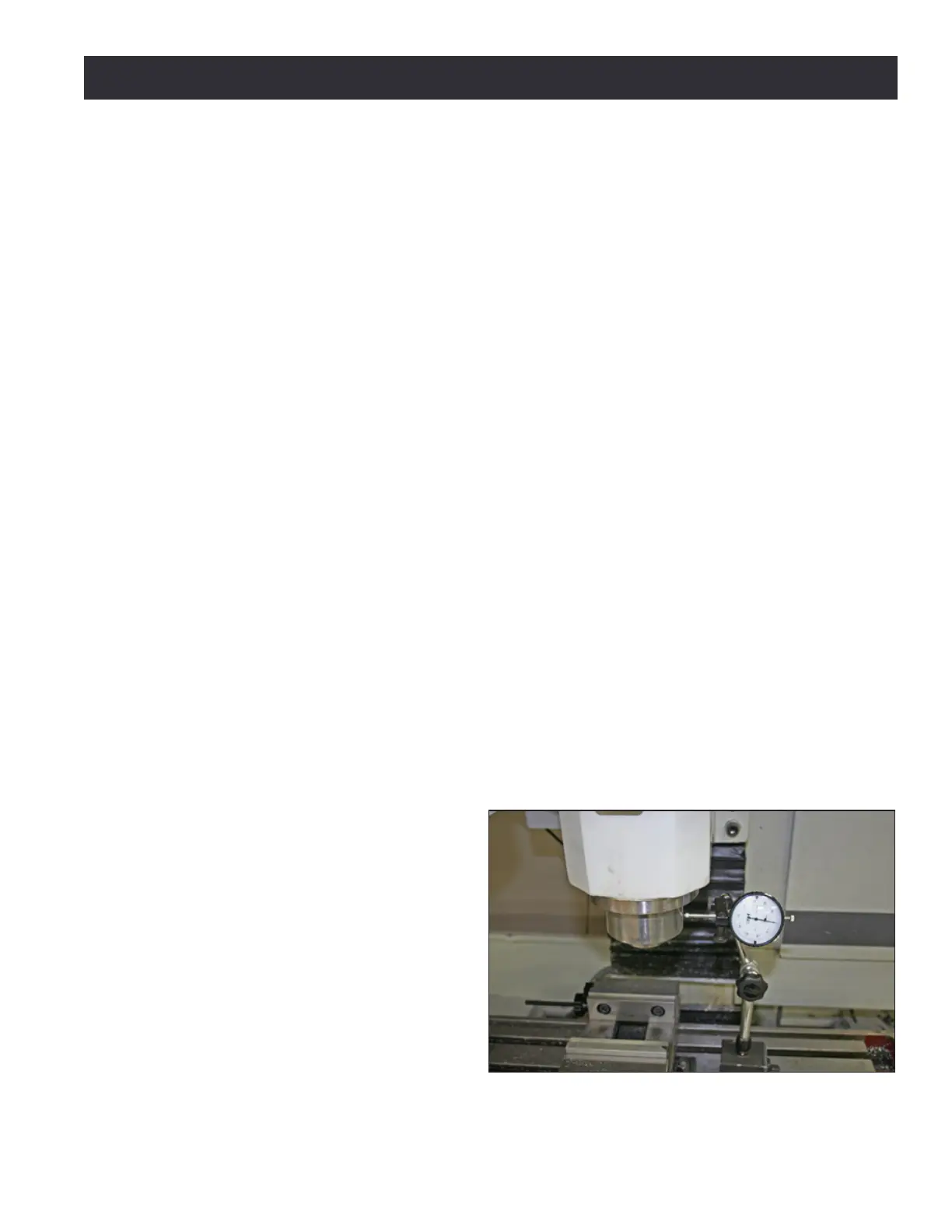
2. Jog the Y- and Z-axis to posion
the spindle head so the indictor p
contacts the outer diameter of the
spindle cartridge (see Figure 9.1).
3. Carefully jog the X-axis in the
posive direcon unl the indictor
contacts the spindle. Aer inial
contact, connue to jog the X-axis
in the posive direcon so that the
dial makes at least one complete
revoluon; stop when dial reads 0.
4. Zero the X DRO eld in PathPilot
®
.
Figure 9.1

 Loading...