Chapter 9
166
UM10349_PCNC1100_Manual_0916A
Maintenance
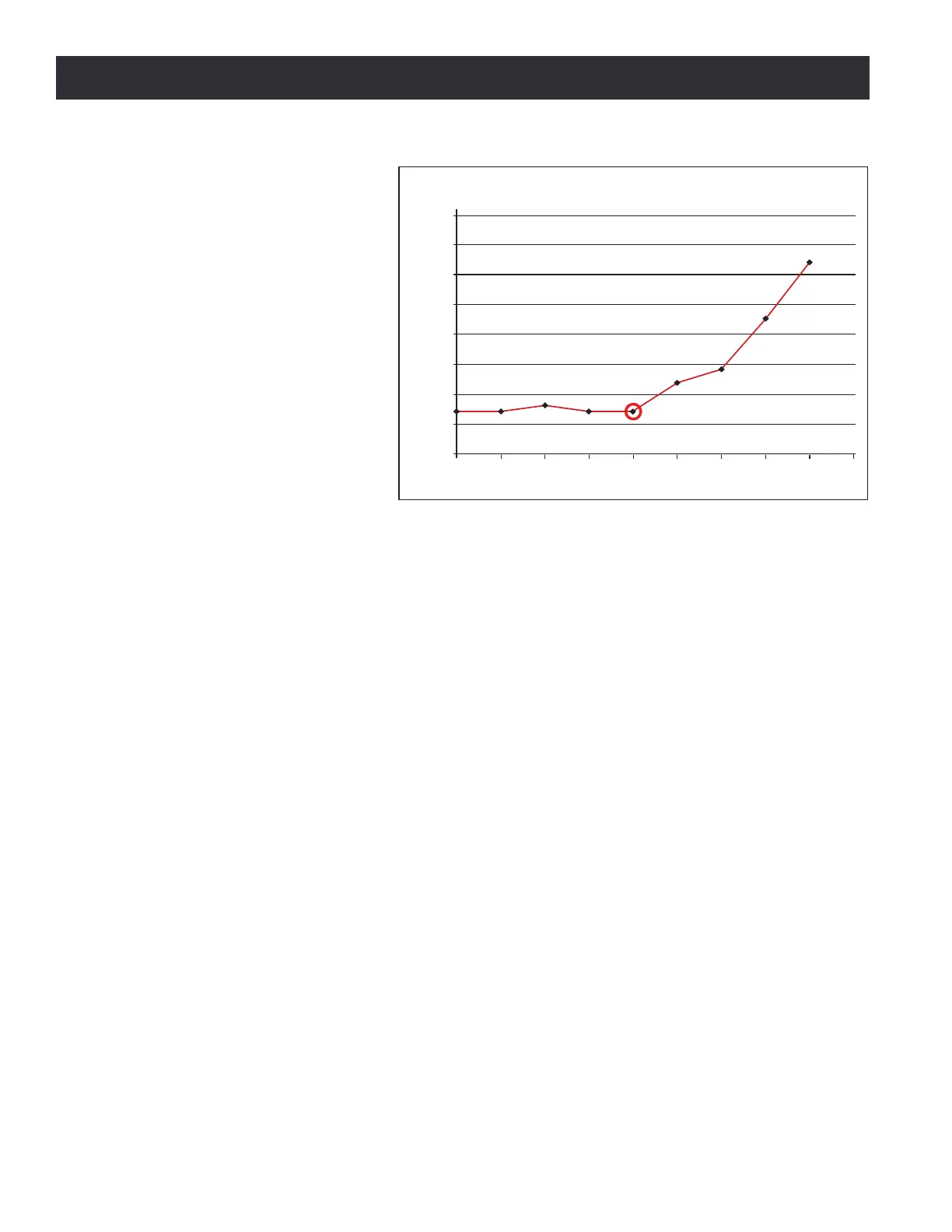
5. Back the adjustment o to
the point just before you
saw the increased backlash.
That is the ideal seng for
the axis (see Figure 9.3).
NOTE: Aer any gib adjustment, ensure
that both adjustment screws are ght
or the gib may move out of adjustment.
9.3.4 Angular Contact Bearing Preload Adjustment
9.3.4.1 Overview
Each axis ulizes a double-nut, pre-loaded ball screw. The pre-load in the ball nut is set at the factory
by placing a precision ground spacer between the two ball nuts. Lost moon aributable to the ball
screw assembly is less than 0.0004”. Ball nut preload is not operator-adjustable.
The ball screw mount bearings are located near the driven (motor) end of each ball screw. These
are a pre-loaded angular contact bearing pair and are operator-adjustable. Under typical use, these
bearings should be adjusted so that observable lost moon is between 0.0005” to 0.0013”.
Figure 9.4 and Figure 9.5 show a cross secon of a typical ball screw sha mount. The ball screw
sha is in the center and the crosshatched secon in Figure 9.5 is the axis motor mount that houses
the bearings. There are two angular contact ball bearings, forming a pre-loaded pair. The ball screw
Cover Plate holds the two outer races together, along with the Spacer that is between them.
The inner races are held between the Sleeve (le side) and the shoulder cut into the ball screw sha
(right side). The Sleeve is held against the le inner bearing race by the Adjustment Nut and a Lock
Nut. When the Adjustment Nut is screwed ghter toward the bearing pair, the preload increases.
Over me, it may become necessary to adjust the ball screw bearing preload to account for bearing
wear. The bearing preload will also need to be adjusted if a bearing replacement becomes necessary.
Improper ball screw bearing preload will result in either excessive backlash in the mill if it is too
loose, or rapid wear and excessive fricon if it is too ght. It should be noted that if your ball screw,
ball nut, or angular contact bearings are worn, or if your gibs are adjusted too ght, you will not
achieve appropriate lost moon values.
0.004
0.0035
0.003
0.0025
0.002
0.0015
0.001
0.0005
0
0 0.5 1 1.5 2 2.5 3 3.5 4 4.5
Backlash (in)
Backlash Versus Turns of Adjusting Screw
Number of Turns of Adjusting Screw
(0 represents a loose gib, 5 represents a tight gib)
Figure 9.3