1. Disconnect power to the controller.
2. Carefully remove the blown fuse from the PC board.
4. Restore power to the controller.
Specifications
Mechanical
Electrical
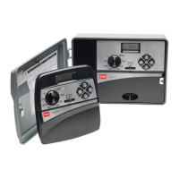
• Cabinet (overall): 10.5" H x 17" W x 6" D
• Wiring Conduit Provisions:
• Operating Temperature Range: 32°F to 140°F (0°C to 60°C)
• Storage Temperature Range: -22°F to 149°F (-30°C to 65°C)
• Input: 120 VAC, 50/60 Hz, 0.5A (24 W max.)
•
•
• Master Valve/Pump Start Relay Output: 24 VAC, 0.5A
• Rain Sensor Compatability: Normally-closed
!
79
Output (per station): 24 VAC, 50/60 Hz, 0.5A (12 VA max.)
Output (total): 24 VAC, 50/60 Hz, 1.5A (36 VA max.)
CAUTION: The fuse protects the transformer from overload
and subsequent damage due to a short circuit condition.
For continued protection against the risk of controller damage
or fire, replace only with a fuse of the same type.
Ensure power is OFF prior to removing/replacing the fuse.
Fuse Replacement
!
Power - 0.50"/.75” (12.7mm/19mm)
Aux. - 0.50"/1” (12.7mm/25.4mm)
Field - 2.5”/ 3" (64mm/76mm)
• Flow Sensor Compatability: Toro TFS Series or
Data Industrial IR Series
• Fuse: 250V, 2A, Slo-Blo
3. Replace with spare fuse (clipped to PCB) or 250V, 2A (Slo-Blo).