9.Applyslightrearwardpressureonthemotion-control
lever,turntheheadoftheadjustmentboltinthe
appropriatedirectionuntilthecontrolleveriscentered
intheNEUTRAL-LOCKposition(Figure90).
Note:Keepingrearwardpressureontheleverkeeps
thepinattheendoftheslotandallowtheadjustment
bolttomovethelevertotheappropriateposition.
10.Tightenthenutandjamnut(Figure90).
11.Repeatfortheoppositesideofthemachine.
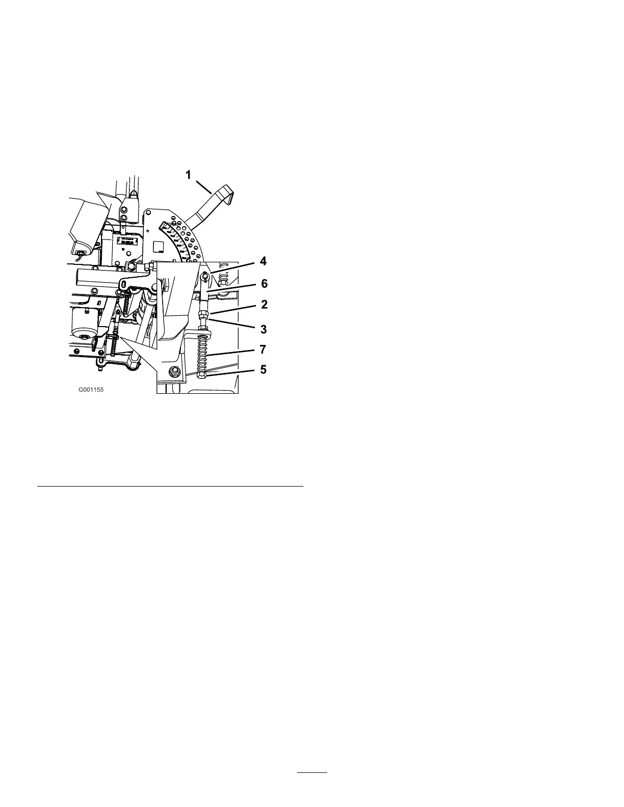
g001155
Figure90
1.Height-of-cutlever
5.Adjustmentbolt
2.Nutagainstyoke6.Yoke
3.Jamnut
7.Spring
4.Clevispininslot
HydraulicSystem
Maintenance
HydraulicSystemSafety
•Ensurethatallhydraulic-uidhosesandlinesarein
goodconditionandallhydraulicconnectionsand
ttingsaretightbeforeapplyingpressuretothe
hydraulicsystem.
•Keepyourbodyandhandsawayfrompinholeleaks
ornozzlesthatejecthigh-pressurehydraulicuid.
•Usecardboardorpapertondhydraulicleaks.
•Safelyrelieveallpressureinthehydraulicsystem
beforeperforminganyworkonthehydraulicsystem.
•Seekimmediatemedicalattentionifuidisinjected
intoskin.Injecteduidmustbesurgicallyremoved
withinafewhoursbyadoctor.
ServicingtheHydraulic
System
Hydraulic-FluidType:Toro
®
HYPR-OIL
™
500hydraulic
uidorMobil
®
115W-50uid
HydraulicSystemFluidCapacity:3.9L(132oz)
Important:Usethespecieduid.Otheruidscould
causesystemdamage.
CheckingtheHydraulic-FluidLevel
ServiceInterval:Aftertherst8hours
Every25hours
Note:Thereare2waysofcheckingthehydraulicuid.One
iswhentheuidiswarmandoneiswhentheuidiscold.
Thebafeinsidethetankhas2levelsdependingiftheuid
iswarmorcold.
1.Positionthemachineonalevelsurfaceandengagethe
parkingbrake.
2.Disengagetheblade-controlswitch(PTO),movethe
motion-controlleverstotheNEUTRAL-LOCKposition,
andengagetheparkingbrake.
3.Shutofftheengine,removethekey,andwaitforall
movingpartstostopbeforeleavingtheoperating
position.
4.Cleantheareaaroundthellerneckofthehydraulic
tank(Figure91).
5.Removethecapfromthellerneckandlookinsideto
checkifthereisuidinthereservoir(Figure91).
6.Ifthereisnouid,adduidtothereservoiruntilit
reachesthecoldlevelofthebafe.
60