WeldingontheMachine
Important:Beforeyouuseanelectricweldertorepair
ormodifythemachine,disconnectallthefollowing
components:
•Thewiringatthealternator.
•The2connectorsforthecomputermodule.
•Theconnectorforthecommand-centerdisplay.
Afteryoucompleteweldingonthemachine,connectthe
alternator,computermodule,andcommand–centerdisplay.
PreparingtoDisconnectthe
Components
1.Removetherightsidepanel;refertoRemovingthe
SidePanels(page45).
2.Rotatethebattery-disconnectswitchtotheOff
position;refertoBattery-DisconnectSwitch(page21).
DisconnectingtheAlternator
Wiring
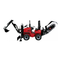
1.Atthealternator,slidethebootofftheterminaland
studatthebackofthealternator(Figure115).
Figure115
1.Chargewire
3.4-socketconnector
(voltage-sensewire)
2.Boot
2.Removethenutandwasherthatsecurestheterminal
ofthechargewiretothestudofthealternator,and
removetheterminal.
3.Removethe4-socketconnectorforthevoltage-sense
wirefromthe4-pinconnectorontopofthealternator
(Figure115).
Disconnectingthe
Computer-moduleConnectors
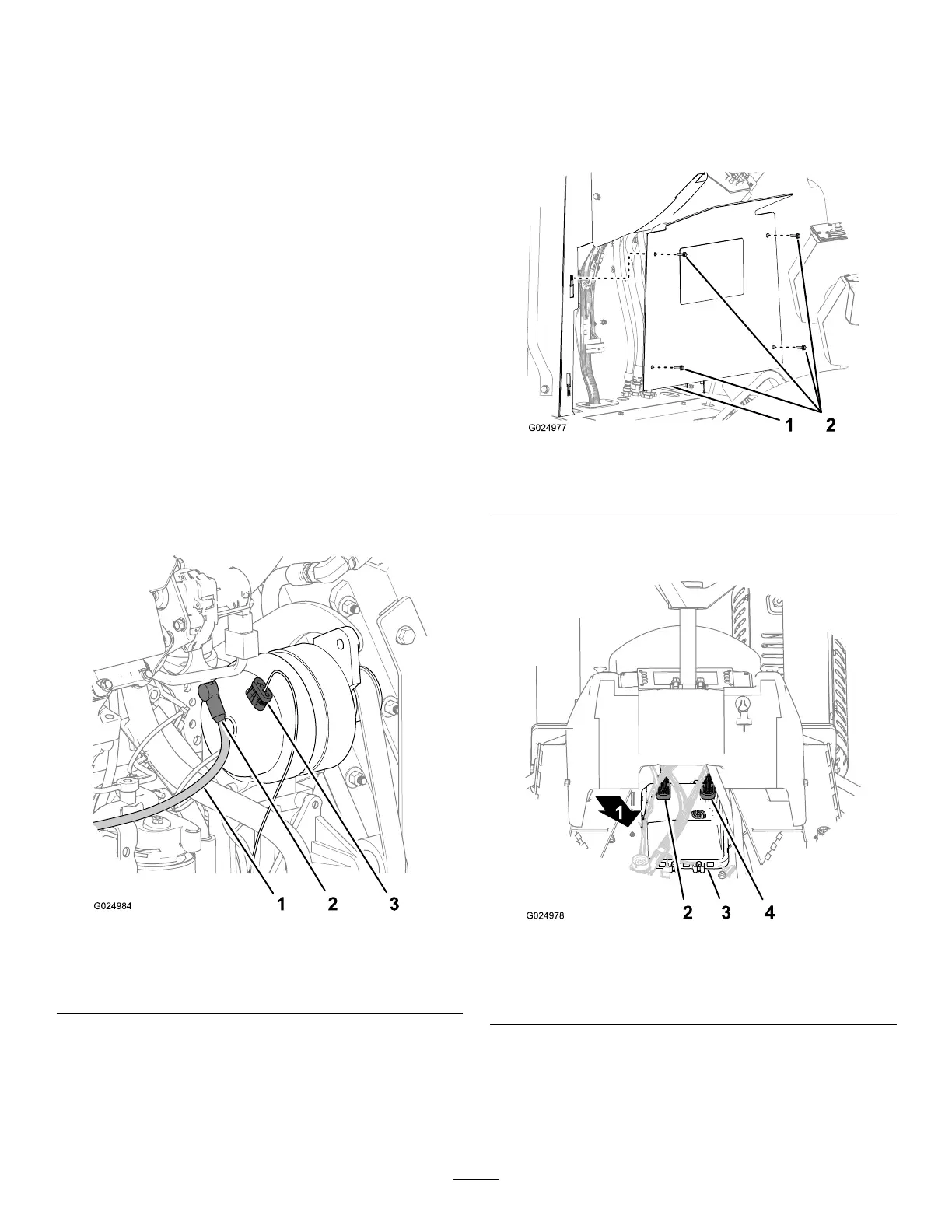
1.Removethe4hex-angedheadbolts(6x20mm)that
securethelower-consolepaneltotheconsole,and
removethepanel(Figure116).
Figure116
1.Lower-consolepanel
2.Hex-angedheadbolts(6
x20mm)
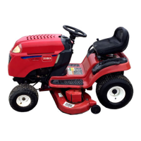
2.Disconnectthe50-socketconnector(CPU1)fromthe
backofthecomputermodule(Figure117).
Figure117
1.Forward
3.Computermodule
2.50-socketconnector(CPU
1)
4.38-socketconnector
(CPU-2)
3.Disconnectthe38-socketconnector(CPU-2)fromthe
backofthecomputermodule(Figure117).
75