61
DE EN
• Batteries must be able to be xed mechanically.
• If mechanical fastening is not possible (e.g. inatable boats without a solid
oor or with a high-pressure air oor), check fastening options with a strap
(tank bracket) or by wedging in narrow stowage spaces.
• It must be possible to install the ventilation adapter in closed storage
rooms or cabins (Power 48-5000 only).
• Select a location that corresponds to the IP protection class of the battery;
information on this can be found in the respective charger unit operating
manual.
• Make sure that the intended installation location offers sufcient space for
the wiring.
Charger units
NOTE! To charge the batteries in the boat, a land connection in the boat with
galvanic isolator is required according to applicable national requirements (e.g.
DIN EN ISO 13297, ABYC E-11).
Keep the following points in mind when planning:
• Torqeedo recommends using one charger unit per battery.
• Choose a place in the boat where there is no stagnant air to ensure cooling
of the charger unit.
• Select a location that corresponds to the IP protection class of the charger
unit; information on this can be found in the respective charger unit operat-
ing manual.
• Make sure that the intended installation location offers sufcient space for
the wiring.
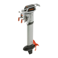
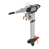
Accelerator lever
If you use a Cruise R, you need an accelerator lever to control the motor.
Keep the following points in mind when planning:
• The accelerator lever must be easily accessible and operable from the
control position.
• The display must be easy to read from the control position.
• The accelerator lever must have enough space to be operated without
restriction.
Emergency kill switch, kill switch, drive enable, on/off switch
Depending on the conguration of your Torqeedo system, you can install differ-
ent components.
Keep the following points in mind when planning:
• Kill switches must be installed near the steering position, this is the only
way the driver can be connected to the kill switch with the rip cord.
• Emergency kill switches must be installed in such a way that they are easily
accessible at all times.
• Plan the installation location of the emergency kill switch so that it cannot
be triggered accidentally (e.g.in downward gradients)
• Plan the installation location of the on/off switch so that there is no danger
of injury (e.g. by getting caught on the key switch)
• Plan the installation location of the switches so that they cannot be acci-
dently actuated.
6.2.2 External loads
Torqeedo recommends that loads that do not affect the Torqeedo system, such as
radios, lighting, etc., should be operated via a separate onboard power supply.
When using external batteries, the energy consumption of auxiliary loads s not
taken into account when calculating the range.
When using auxiliary loads, the additional power consumption must be taken
into account and the battery bank must be designed according to the total power
consumption.
6.2.3 Wiring
The wiring of your Torqeedo system depends on the components installed. You
can nd the connection diagram for your system in the Service Center section of
our website: www.torqeedo.com
Keep the following points in mind when planning:
• An earthing point is required for your Torqeedo system. Take into account
the connection and the cables required for this in your planning. The
required cable cross-sections can be found in the section Tools, equipment
and material.
• First determine and plan the installation positions of all components.
 Loading...